
Physical Range of 90mm LS2 vs 78mm TB
 11-12-2006, 11:33 PM
#11
My logging of the 2 ETCAPP and 2 ETCTP sensor PIDs with EFILive yielded odd results. All 5 sensors logged identically and 100% in sync. The so called sensor outputs all ranged from 0 to 5V with 0 being closed TP/0 APP and 5 being WOT/Max APP. Of course the sensors are all supposed to have differing output ranges and some even move in opposite directions. Not sure if the TAC module converts them all prior to sending the data to the PCM, this is a bug in EFILive or something else. I don't even see why the TAC would bother sending converted voltage values to the PCM via serial data. Why not just send the TP % or APP % if you aren't going to send the true sensor outputs?
APP sensor(?) voltage values are not shown in this screenshot but they were also 1.6V
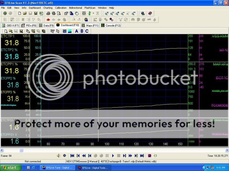
APP sensor(?) voltage values are not shown in this screenshot but they were also 1.6V
Last edited by DrX; 11-12-2006 at 11:55 PM.
 11-13-2006, 10:49 AM
#12

That brings up a few questions that I have:
What actual data does the TAC module send to the PCM? Does it send Pedal and Throttle %s or volts for each?
Does the PCM or the TAC "define" the voltages expected from these sensors? i.e. > If the stock TB sensor 1 has an operating range of .05v closed and 4.5v full open, does the TAC or PCM correlate those volts into percent blade opening?
11-13-2006, 10:51 AM
#13
TECH Apprentice
iTrader: (1)

Join Date: May 2003
Location: Keller, TX
Posts: 339
Likes: 0
Received 0 Likes
on
0 Posts
Originally Posted by DrX
Has anybody looked at their 78mm to see if it opens any more than the LS2 TB?
Played around with both today and this is what I saw. I also logged PIDs for the APP sensors and TP sensors. The logged values did not reflect the described operation of the sensors as per the service manual. So I believe that all of the interpretation of sensor inputs is done in the TAC module.
Played around with both today and this is what I saw. I also logged PIDs for the APP sensors and TP sensors. The logged values did not reflect the described operation of the sensors as per the service manual. So I believe that all of the interpretation of sensor inputs is done in the TAC module.
but the 90mm with the supplied 2002 TAC and harness will only open 85%.
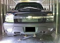
here's the pics:
78MM

90MM
 11-13-2006, 07:11 PM
#14
DrX, Curious, what TAC module was used with each? When I swapped out I used the 02 TAC module.
Wondering if I would see the same results you did in your video if I plugged up the 78mm TB it wouldn't open all the way using the 02 TAC. But if I were to plug the 03 TAC back in the 78mm would open all the way.
Wondering if I would see the same results you did in your video if I plugged up the 78mm TB it wouldn't open all the way using the 02 TAC. But if I were to plug the 03 TAC back in the 78mm would open all the way.
11-13-2006, 07:57 PM
#15
Originally Posted by KySilverado
DrX, Curious, what TAC module was used with each? When I swapped out I used the 02 TAC module.
Wondering if I would see the same results you did in your video if I plugged up the 78mm TB it wouldn't open all the way using the 02 TAC. But if I were to plug the 03 TAC back in the 78mm would open all the way.
Wondering if I would see the same results you did in your video if I plugged up the 78mm TB it wouldn't open all the way using the 02 TAC. But if I were to plug the 03 TAC back in the 78mm would open all the way.
I used the 02 TAC module with the LS2-90mm and my OE 04 TAC module with the OE 78mm. If you use the wrong TAC module it will initiate REP mode and the TP will remain in the Park position(around 20%) and not respond to pedal position. The 02 TAC module is designed to work with a TB that has the 2 TP sensor outputs moving in opposite directions. In subsequent years the 78mm TP sensors both move in the same direction(output voltage increases as the throttle opens). Although the LS2 and 02 78mm TP sensors do have different operating output ranges. I seem to recall reading somewhere that some sensor range learning may be involved. Maybe that's why it still works.
I did a PCM reflash between the tests because I was concerned about the possible learning issue. But I am wondering if the learning takes place within each TAC module itself.
Last edited by DrX; 11-13-2006 at 08:04 PM.
11-13-2006, 09:28 PM
#17
FormerVendor
iTrader: (3)

Join Date: May 2002
Location: Reseda, CA
Posts: 1,853
Likes: 0
Received 0 Likes
on
0 Posts
Can someone tell me if the stock 78mm ttb is a parabolic design like the 90mm? The blade on the 90mm units has to rotate quite a long way before exposing the major portion of the throttle bore. Could the extra travel be causing the difference?
Great work here. Thank you guys a ton!
Richard
Great work here. Thank you guys a ton!
Richard

 11-13-2006, 10:59 PM
#19
TECH Apprentice

Join Date: Nov 2006
Location: Juda
Posts: 335
Likes: 0
Received 0 Likes
on
0 Posts
I just bought an 03 1500HD and the first 30% of the throttle feels like milk toast. It drives me crazy. What equipment are you using to change/monitor all of these things on your trucks. Is it a laptop? what kind of software are you using. I'm trying to read and understand all of this stuff but my head is swimming.
I live in SW Wisconsin. Is there anyone local that can help me out with all of these tuning concepts? Thanks.
I live in SW Wisconsin. Is there anyone local that can help me out with all of these tuning concepts? Thanks.
11-13-2006, 11:08 PM
#20
Some background from the service manuals:
02 TAC Description and Operation:
The TAC module is the control center for the electronic throttle system. The TAC module and the powertrain control module (PCM) communicate via a dedicated redundant serial data circuit. The TAC module and the PCM monitor the commanded throttle position and compare the commanded position to the actual throttle position. This is accomplished by monitoring the APP and the TP sensor. These 2 values must be within a calibrated value of each other. The TAC module also monitors each individual circuit of the TP sensor and the APP to verify proper operation.
04 TAC Description and Operation(a little more info in this one):
Throttle Actuator Control Module
The throttle actuator control (TAC) module is the control center for the throttle actuator control system. The TAC system is self-diagnosing and provides diagnostic information to the powertrain control module (PCM) through a dedicated serial data line. The TAC achieves throttle positioning by providing a pulse width modulated voltage to the TAC, as directed by the PCM.
Powertrain Control Module
The powertrain control module (PCM) determines the driver's intent, then calculates the appropriate throttle response. This information is sent to the throttle actuator control (TAC) module through a dedicated serial data line.
Modes of Operation
Normal Mode
During the operation of the throttle actuator control (TAC) system, several modes or functions are considered normal. The following modes may be entered during normal operation:
When the PCM detects a condition with the TAC system, the PCM may enter a reduced engine power mode. Reduced engine power may cause one or more of the following conditions:
02 TAC Description and Operation:
The TAC module is the control center for the electronic throttle system. The TAC module and the powertrain control module (PCM) communicate via a dedicated redundant serial data circuit. The TAC module and the PCM monitor the commanded throttle position and compare the commanded position to the actual throttle position. This is accomplished by monitoring the APP and the TP sensor. These 2 values must be within a calibrated value of each other. The TAC module also monitors each individual circuit of the TP sensor and the APP to verify proper operation.
04 TAC Description and Operation(a little more info in this one):
Throttle Actuator Control Module
The throttle actuator control (TAC) module is the control center for the throttle actuator control system. The TAC system is self-diagnosing and provides diagnostic information to the powertrain control module (PCM) through a dedicated serial data line. The TAC achieves throttle positioning by providing a pulse width modulated voltage to the TAC, as directed by the PCM.
Powertrain Control Module
The powertrain control module (PCM) determines the driver's intent, then calculates the appropriate throttle response. This information is sent to the throttle actuator control (TAC) module through a dedicated serial data line.
Modes of Operation
Normal Mode
During the operation of the throttle actuator control (TAC) system, several modes or functions are considered normal. The following modes may be entered during normal operation:
- Minimum pedal value--At key-up the powertrain control module (PCM) updates the learned minimum pedal value.
- Minimum throttle position (TP) values--At key-up the PCM updates the learned minimum TP value. In order to learn the minimum TP value, the throttle blade is moved to the closed position.
- Ice break mode--If the throttle is not able to reach a predetermined minimum throttle position, the ice break mode is entered. During the ice break mode, the control module commands the maximum pulse width several times to the throttle actuator motor in the closing direction.
- Battery saver mode--After a predetermined time without engine RPM, the control module commands the battery saver mode. During the battery saver mode, the TAC module removes the voltage from the motor control circuits, which removes the current draw used to maintain the idle position and allows the throttle to return to the spring loaded default position.
When the PCM detects a condition with the TAC system, the PCM may enter a reduced engine power mode. Reduced engine power may cause one or more of the following conditions:
- Acceleration limiting--The control module will continue to use the accelerator pedal for throttle control; however, the vehicle acceleration is limited.
- Limited throttle mode--The control module will continue to use the accelerator pedal for throttle control; however, the maximum throttle opening is limited.
- Throttle default mode--The control module will turn off the throttle actuator motor and the throttle will return to the spring loaded default position.
- Forced idle mode--The control module will perform the following actions:
- Limit engine speed to idle by positioning throttle position, or by controlling fuel and spark if throttle is turned off.
- Ignore accelerator pedal input.
- Engine shutdown mode--The control module will disable fuel and de-energize the throttle actuator.