
Physical Range of 90mm LS2 vs 78mm TB
 11-18-2006, 12:38 PM
#41
Originally Posted by BigTex
I was just reading over some of the GM service manuals for various electric driven TB vehicles. Although it didn't come outright and say this, one statement I read made me think the PCM only watches sensor 1 for the TB and the pedal. The TAC on the other hand monitors the relationship between the sensor 1 and sensor 2 and reports back to the PCM that everything is in proper order. Out stock TB and the LS2 stuff have sensor 1 going in the same direction, which is why the PCM works with the LS2 parts. The TAC on the other hand is concerned about sensor 2, which is why it needs to be swapped out with the LS2 parts.

 11-18-2006, 01:57 PM
#43

Would it be possible to reduce voltage just a bit on the +5v reference wire that feeds the TB (without setting a code)? If so, then the LS2 potentiometer that registers 4.2v could be scaled back to 3.9v at full throttle. Since the LS2 uses only one +5 and ground, a single change would scale both sensors. That would also reduce low values to something below .5v, which might register a fault with the TAC.
11-18-2006, 05:19 PM
#44
Originally Posted by BigTex
Would it be possible to reduce voltage just a bit on the +5v reference wire that feeds the TB (without setting a code)? If so, then the LS2 potentiometer that registers 4.2v could be scaled back to 3.9v at full throttle. Since the LS2 uses only one +5 and ground, a single change would scale both sensors. That would also reduce low values to something below .5v, which might register a fault with the TAC.
After you suggested that the PCM may only look at TPS1, I tried turning off the ETC DTC enablers but still got REP mode with the TB unplugged. No DTCs were set. Seems that the PCM thinks that proper TB operation is important. I'll keep them off for now. I have a couple more things to try.
11-19-2006, 12:40 AM
#46
TECH Addict
iTrader: (5)

Join Date: Apr 2002
Location: Poulsbo, WA
Posts: 2,381
Likes: 0
Received 0 Likes
on
0 Posts
Originally Posted by BigTex
I wonder if the stock TAC would work with the LS2 TB if the DTCs were disabled. The PCM would still be getting proper sensor input from sensor 1.
I've been playing with max ported LS2 TB's on my truck (with the TAC module swap)and found out some crappy things.
I have found that when you really start working the LS2 TB hard that you can cause TB position errors that result in Reduced Engine Power mode. The only way these can be occuring is if there are still more unseen airflow vs TB position tables buried in the code. Maybe they are MAP vs TB angle? Anyway, too much flow and the pcm decides there must be a TB angle error. Even maxing out all the available diagnostic tables dealing with airflow cannot stop the REP mode from happening.
I even disabled the codes I was seeing. It did stop me from getting the codes... but the REP would just set anyway. Soo... disabling codes does not prevent REP with the TAC swap and likely does not prevent the REP on the stock one either.
On a side note... I sure would like to be able to turn off REP mode.
11-19-2006, 11:18 AM
#47
Originally Posted by CHarris
I've been doing some research down another TB tangent tht seems to have yielded some info that might help here. I've got to say I dont think the code disabling will work.
I even disabled the codes I was seeing. It did stop me from getting the codes... but the REP would just set anyway. Soo... disabling codes does not prevent REP with the TAC swap and likely does not prevent the REP on the stock one either.
I even disabled the codes I was seeing. It did stop me from getting the codes... but the REP would just set anyway. Soo... disabling codes does not prevent REP with the TAC swap and likely does not prevent the REP on the stock one either.
11-19-2006, 11:33 AM
#48
Originally Posted by BigTex
I wonder if the stock TAC would work with the LS2 TB if the DTCs were disabled. The PCM would still be getting proper sensor input from sensor 1.
I have modded the LS2 TB to use separate 5V and low reference circuits for each sensor as in the 78mm TBs. So far I am able to get past the key-on test and can make it up to 30-45 % TP before losing the correlation and triggering REP. This is using the 04 TAC module. Of course this has nothing to do with acheiving 100% opening yet but it might help develop a better understanding of how the system operates. With separate circuits I can vary the input voltage to one sensor without affecting the other. Going to play with the 02 TAC module as well.
Here's a couple of pics of the TP sensor arrangement in the 90mm:
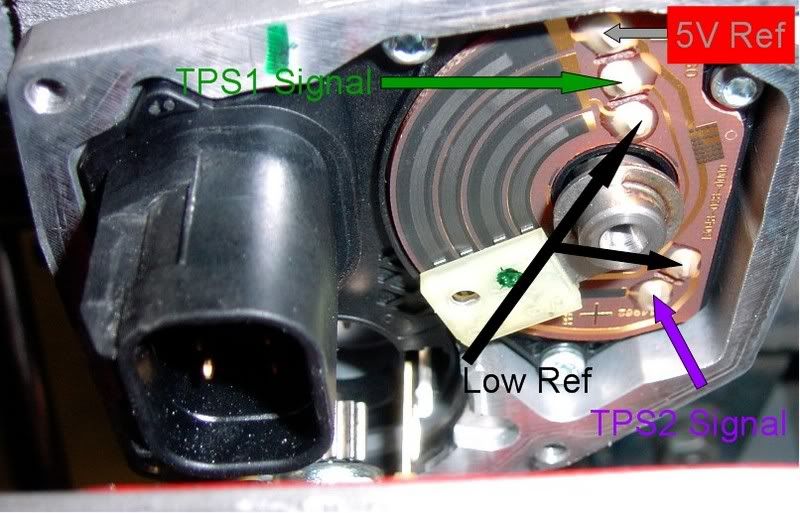
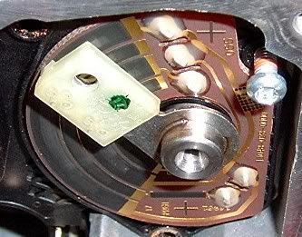
This looks like it may be where resistance is added in the crossover of the common 5V ref in order to acheive proper correlation between the 2 sensors:
 11-19-2006, 01:11 PM
#49
Interesting. I've been under the assumption for the past year and a half that the LS2 TB was the same internal design as the SSR TB. Physically, the SSR TB is a much closer match to the stock truck TB. None of the parts are interchangeable and they are made by different manufacturers, but they have basically the same design. As you can see from these pictures, the SSR TB uses a potentiometer film and wiper setup just like the trucks use, with the exception of the single +5v and ground reference setup.
SSR LS2 TB on the left side, stock truck on the right:


In this pic, you can see the layout of both sensor films, with the truck 78 on top with 6 connections and the LS2 SSR on the bottom showing only 4 connections. Physically the film is identical in size.

Here you can see the films for each and the wiper that goes with each one. The SSR has a small post on the blade shaft, while the trucks shaft is quite larger and is keyed in a different direction. That would make it difficult (but not impossible) to swap wiper and films between the two.

Here is a picture of the SSR TB with the sensors exposed. The wiper film is on the inside of the half moon and the wipers sweep back and forth as the blade rotates.

It may be possible to swap films with the stock truck TB and use the SSR wiper which may need slight alteration to keep proper contact with the film. Then, you'd need to cut open the exterior behind the sensor connection pins and wire up the 6 connections properly. Add in the 2 PWM TB motor wires and you'd have all 8 connections. Unfortunately this would mean a hacked up TB, but then you wouldn't need the extra TAC or harness adapter.
SSR LS2 TB on the left side, stock truck on the right:
In this pic, you can see the layout of both sensor films, with the truck 78 on top with 6 connections and the LS2 SSR on the bottom showing only 4 connections. Physically the film is identical in size.
Here you can see the films for each and the wiper that goes with each one. The SSR has a small post on the blade shaft, while the trucks shaft is quite larger and is keyed in a different direction. That would make it difficult (but not impossible) to swap wiper and films between the two.
Here is a picture of the SSR TB with the sensors exposed. The wiper film is on the inside of the half moon and the wipers sweep back and forth as the blade rotates.
It may be possible to swap films with the stock truck TB and use the SSR wiper which may need slight alteration to keep proper contact with the film. Then, you'd need to cut open the exterior behind the sensor connection pins and wire up the 6 connections properly. Add in the 2 PWM TB motor wires and you'd have all 8 connections. Unfortunately this would mean a hacked up TB, but then you wouldn't need the extra TAC or harness adapter.
11-19-2006, 03:24 PM
#50
TECH Addict
iTrader: (5)
Join Date: Apr 2002
Location: Poulsbo, WA
Posts: 2,381
Likes: 0
Received 0 Likes
on
0 Posts
Damn... Big Tex has been busy! Interesting stuff for sure!
I'm starting to look at airflow differences between the LS2 car TB and the LS2 SSR TB. I've been porting out my SSR TB in stages to see what happens as the "big bump" gets removed. My belief is that the step that restricts airflow is only there for increased throttle response in that it causes you to apply more throttle to get more airflow. A reduced step allows more airflow sooner thereby decreasing your "pedal resolution". I don't believe most of us are too concerned with pedal resolution as most of us don't do a lot of rock crawling type maneuvers that really require good throttle modulation. My belief right now is that the SSR TB can be made as good as the LS2 car TB. I'll report my findings later in another thread when I'm done.
I'm starting to look at airflow differences between the LS2 car TB and the LS2 SSR TB. I've been porting out my SSR TB in stages to see what happens as the "big bump" gets removed. My belief is that the step that restricts airflow is only there for increased throttle response in that it causes you to apply more throttle to get more airflow. A reduced step allows more airflow sooner thereby decreasing your "pedal resolution". I don't believe most of us are too concerned with pedal resolution as most of us don't do a lot of rock crawling type maneuvers that really require good throttle modulation. My belief right now is that the SSR TB can be made as good as the LS2 car TB. I'll report my findings later in another thread when I'm done.