
Physical Range of 90mm LS2 vs 78mm TB
 11-25-2006, 11:56 PM
#71
Did a 15 minute test run tonight. Seems to be working great for the most part. 12*F ambient temps help though(12 psi on a 3.25" pulley).
Did have an incident of REP near the end while coasting after a short burst on an on ramp. Appears to be due to an intermittent connection in the TPS2 circuit based on a couple of blips in the log and the DTCs set. Have to check the temporary T-tap as everything else is soldered. I did have issues with those during testing.
Cold startups will be the real test. Right now I have the throttle area conversion factor set to what it theoretically should be for the 90mm TB. Worked well in the garage but that doesn't tell me much. Previously I had to use a value even higher than that for the 78mm to prevent stalling on a cold start(below freezing) P > D shift.
A completely external "black box" solution to this issue would probably require modulation of the TPS signals themseves. This is difficult(for me anyway) because the correlation between the 2 sensors has to be maintained while they are moving in opposite directions. Also, there is a voltage of 2.X Volts at the TAC module end of the sensor wires even without any input from the sensors. It would probably be easiest to get both signals going in the same direction first (so the 02 TAC module would not be required). Possibly by inverting one signal(i.e. to a negative voltage) and adding it back to the 5V ref. I attempted this using an op amp circuit but it was a no go. Could of had a poor connection somewhere or could be due to the fact that I have never heard of an op amp until this past week. Once both signals are moving in the same direction and in synch, then it should be easy to bring them both down equally. I'll leave this to the electronics experts.
I did try modifying the sensor circuits themselves to have them move in the same direction but I was losing the correlation after 45% commanded TP. This aproach still involves opening up the TB though.
I'll post my method tomorrow. It might give someone else some ideas as well.
 11-23-2010, 03:01 PM
#73

I am trying to do the oposite of what you are doing, I am using a E40 LS2 computer to control a 78mm LS1 truck style throttle body.
6 pin 8 PIN
A 582 C 582
B 581 A 581
C 1704 B&H 1704 & 416
D 485 G 485
E 1688 D&E 452 & 1688
F 486 F 486
-wiht the key on multi meter black probe on 6 pin C 1704 low refernce and the red probe on d 485 tps1. I get 3 volts closed and 0 volts WOT
-wiht the key on multi meter black probe on 6 pin C 1704 low refernce and the red probe on F 486 tps2. I get o volts closed and 3 volts WOT
So I am getting them to move in the oposite directions like the E40 PCM wants how ever the PCM never moves the throttle blade at all so it is at rest in the slightly open postion, also my multimeter round voltages up or down, to the nearest volt, so I might be getting 3.4999 volts and .499 volts instead of 3 volts and zero volts.
I am getting codes;
[ECM] P2119 - Throttle Actuator Control Throttle Body Range/Performance (Pending) (History) (Current) (Immature)
[ECM] P2138 - Throttle/Pedal Position Sensor/Switch D/E Voltage Correlation (SES) (Pending) (History) (Current) (Immature)
the engine will start but only in REP mode.
My question is do yo know what the resister or diode is that you said is between the 5 volt refernce line? I may need to replicate that. Also are there anything seporating the low refernce lines resistor or diode? THanks Jamie
I have been playing with the stock TAC module. It's not happy when there is only one sensor signal. And REP is still triggered even with the DTCs disabled.
I have modded the LS2 TB to use separate 5V and low reference circuits for each sensor as in the 78mm TBs. So far I am able to get past the key-on test and can make it up to 30-45 % TP before losing the correlation and triggering REP. This is using the 04 TAC module. Of course this has nothing to do with acheiving 100% opening yet but it might help develop a better understanding of how the system operates. With separate circuits I can vary the input voltage to one sensor without affecting the other. Going to play with the 02 TAC module as well.
Here's a couple of pics of the TP sensor arrangement in the 90mm:
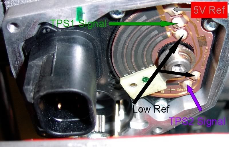
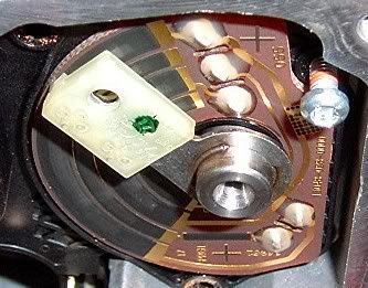
This looks like it may be where resistance is added in the crossover of the common 5V ref in order to acheive proper correlation between the 2 sensors:

I have modded the LS2 TB to use separate 5V and low reference circuits for each sensor as in the 78mm TBs. So far I am able to get past the key-on test and can make it up to 30-45 % TP before losing the correlation and triggering REP. This is using the 04 TAC module. Of course this has nothing to do with acheiving 100% opening yet but it might help develop a better understanding of how the system operates. With separate circuits I can vary the input voltage to one sensor without affecting the other. Going to play with the 02 TAC module as well.
Here's a couple of pics of the TP sensor arrangement in the 90mm:
This looks like it may be where resistance is added in the crossover of the common 5V ref in order to acheive proper correlation between the 2 sensors:
11-23-2010, 07:35 PM
#74
This is an old one!
It shouldn't be that difficult to do what you want because the TPS circuits in the 78mm TB are completely separate.
The factory pinout for the 78mm causes the 2 TPS signals to move in the same direction. Your ECM is looking for the 2 sensor signals to be moving in opposite directions so first you will have to switch the +5V and 0V references around for one of the TPS circuits. The signal range and synchronization will still have to be within what the ECM is expecting though.
11-23-2010, 10:37 PM
#76
this is the same right?
6 pin 8 pin
A582 C 582 tac motor 2
B 581 A 581 tac motor 1
C 1704 D&E 452 & 1688 low ref. joined too low ref and 5 volt ref.
D 485 G 485 TP sen 1
E 1688 B & H 1704 & 416 5 volt ref. joined to low ref and 5 volt ref.
F 486 F 486 TP sen 2
I will give this a try but it should do exactly opisite of what I posted earlier so I should get;
TPS1 0 volts closed and 3 volts WOT
TPS2 3 volts closed and 0 volts WOT
isn't this oposite of what the PCM is looking for? don't we want TPS1 above 4 volts closed, and 0 volts WOT, TPS2 O volts close and 3 or higher volts WOT?
I am still concerned about code P2138 1-2 correlaton D and E pedal postion sensor.
Thanks for you help, I will try what you said anyway just to see if it may work! -Jamie
11-23-2010, 11:21 PM
#77
this is the same right?
6 pin 8 pin
A582 C 582 tac motor 2
B 581 A 581 tac motor 1
C 1704 D&E 452 & 1688 low ref. joined too low ref and 5 volt ref.
D 485 G 485 TP sen 1
E 1688 B & H 1704 & 416 5 volt ref. joined to low ref and 5 volt ref.
F 486 F 486 TP sen 2
I will give this a try but it should do exactly opisite of what I posted earlier so I should get;
TPS1 0 volts closed and 3 volts WOT
TPS2 3 volts closed and 0 volts WOT
isn't this oposite of what the PCM is looking for? don't we want TPS1 above 4 volts closed, and 0 volts WOT, TPS2 O volts close and 3 or higher volts WOT?
I am still concerned about code P2138 1-2 correlaton D and E pedal postion sensor.
Thanks for you help, I will try what you said anyway just to see if it may work! -Jamie
6 pin 8 pin
A582 C 582 tac motor 2
B 581 A 581 tac motor 1
C 1704 D&E 452 & 1688 low ref. joined too low ref and 5 volt ref.
D 485 G 485 TP sen 1
E 1688 B & H 1704 & 416 5 volt ref. joined to low ref and 5 volt ref.
F 486 F 486 TP sen 2
I will give this a try but it should do exactly opisite of what I posted earlier so I should get;
TPS1 0 volts closed and 3 volts WOT
TPS2 3 volts closed and 0 volts WOT
isn't this oposite of what the PCM is looking for? don't we want TPS1 above 4 volts closed, and 0 volts WOT, TPS2 O volts close and 3 or higher volts WOT?
I am still concerned about code P2138 1-2 correlaton D and E pedal postion sensor.
Thanks for you help, I will try what you said anyway just to see if it may work! -Jamie
So there are 2 ways to do it:
Pin A Motor 1
Pin B 5V
Pin C Motor 2
Pin D 0V
Pin E 0V
Pin F TPS1
Pin G TPS2
Pin H 5V
or
Pin A Motor 1
Pin B 0V
Pin C Motor 2
Pin D 5V
Pin E 5V
Pin F TPS2
Pin G TPS1
Pin H 0V
11-24-2010, 12:53 AM
#78
Ok then I have basiclly tried this allready, I wonder if the problem is that the PCm wants over 4 volts instead of 3.5 volts which I am getting on TPS1 closed throttle. Waht would happen if I put in a resister on the low refernece side, could this trick the pcm into sending out more voltage on the 5 volt ref line and intern recive a higher reading from the TPs1 sensor circuit? Other wise how else can I get 3.5 volts up to 4.xx volts?
Yes, you would also have to swap the TPS1 and TPS2 pins if you do that. It doesn't really matter which one you use as TPS1 and 2 as they should both behave the same. You just have to make sure that one is high at closed throttle and the other is low, then correct them to the correct circuits to the ECM.
So there are 2 ways to do it:
Pin A Motor 1
Pin B 5V
Pin C Motor 2
Pin D 0V
Pin E 0V
Pin F TPS1
Pin G TPS2
Pin H 5V
or
Pin A Motor 1
Pin B 0V
Pin C Motor 2
Pin D 5V
Pin E 5V
Pin F TPS2
Pin G TPS1
Pin H 0V
So there are 2 ways to do it:
Pin A Motor 1
Pin B 5V
Pin C Motor 2
Pin D 0V
Pin E 0V
Pin F TPS1
Pin G TPS2
Pin H 5V
or
Pin A Motor 1
Pin B 0V
Pin C Motor 2
Pin D 5V
Pin E 5V
Pin F TPS2
Pin G TPS1
Pin H 0V

 good tech info here!