When you click on links to various merchants on this site and make a purchase, this can result in this site earning a commission. Affiliate programs and affiliations include, but are not limited to, the eBay Partner Network.
This website has been good to me so I figured I would give back. Today I installed a set of 3.73 gears and Detroit Tru-Track in PasadenaMan's truck.
Given all the questions that are asked about this I figured I would take pictures of a gear install I did and share the knowledge. THIS IS FOR THE GM 8.5/8.6 REAR END (10 BOLT), however the principles discussed can be applied to any axle.
First off, this is information only, use it at your own risk. What will be described below is how I do gear installs. I am not responsible for anything that results from whoever decides to use this.
READ THIS WRITE UP AND ANY RECOMMENDED MATERIAL FULLY BEFORE ATTEMPTING A GEAR SWAP/INSTALL. IF THIS IS YOUR FIRST TIME, MAKE SURE YOU HAVE THE WHOLE WEEKEND AT YOUR DISPOSAL.
There are 4 major settings when installing gears. They are:
Now for some math. Hopefully this will prevent many more "What Gear?" threads.
So you have changed your tire size and need to know what gear to upgrade too. Use this equation:
New Ratio = Current Ratio * (New Tire Dia./Old Tire Dia.)
Select the next lowest gear ratio to ensure that you are not undergeared. The above equation will put you close stock performance.
Now for the install awesomeness.
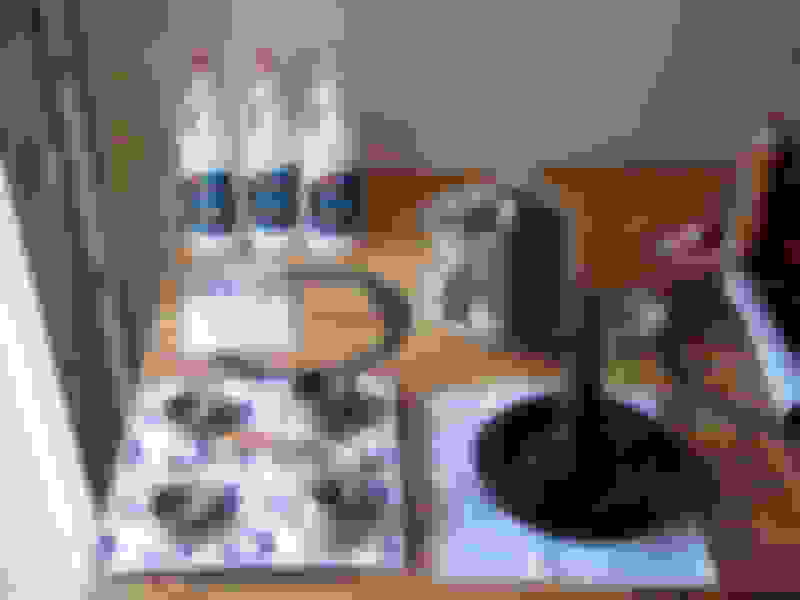
At the minimum, to do this right you will need everything you see in the pic:
What you see is:
1. Ring and pinion
2. Master Install Kit
3. 3 QTS of NAME BRAND non-synthetic 80W-90 gear oil (don't need synthetic for break-in)
4. Yukon Gear Install Manual
5. Gasket
6. Differential (optional, a lot of people reuse their old differential)
The Yukon Gear Install Manual is a free download from randysringandpinion.com. It is highly recommended that you read this manual as it contains additional tips, pictures of many acceptable and unacceptable contact patterns, and the torque specs for most axles.
Aside from sockets, wrenches, hammer, assorted punches, jack and jackstands, you will need specialty tools to do the swap without worries. Some claim to never use these tools and say that they have never had any problems. Fair enough. I like to finish the job without doubts, so I use these tools. A major plus is that they are not expensive. Everything you see below was purchased at Harbor Freight with the acception of the inch pound torque wrench which was purchased from Randy's R&P.
1. Dial Indicator and Magnetic Base
2. Dial Calipers
3. Set-up Bearings
4. Gear Paint
5. Inch Pound Bar Type Torque Wrench
6. Shop Press (Not necessary but makes this MUCH easier)
I like to start by assembling the differential. ALWAYS use NEW ring gear bolts. Also, DO NOT use the ring gear bolts to pull the ring gear into place. What I like to do is put the ring gear on as far as I can, loosley thread 2 bolts to guide the ring gear, and use my press to seat the ring gear in the differential. If you do not have a press, a block of wood and hammer will work. Use thread locker on all the bolts and tighten in a criss cross pattern to 65 ft. lbs.
Afterwards I press on the carrier bearings. I use a combination of my press, a bearing driver kit, and an old bearing race to press the carrier bearings on. Again, if you don't have a press, a hammer in conjuction with the above mentioned tools will get the job done.
Now it is time to tear into the truck. Use common sence and put wheel chocks or wood around the front tires to keep the truck from moving. I like to be comfortable so I use BIG jackstands to get the truck high enough for me to sit under it. The jackstands in the picture below can be had at Harbor Freight or Northern Tool.
1. Remove the wheels.
2. Remove the calipers if you have rear disks (18 mm wrench) or slide the drums off.
3. Remove the differential cover (13 mm socket) and drain the oil.
4. Remove the differential center pin lock bolt (8 mm socket or wrench).
5. Remove the differential center pin.
6. Slide the axles towards the center of the truck, pull the C-clips and slide the axle shafts out far enough to where you can remove the differential.
7. Disconnect the driveshaft (11 mm socket or wrench).
8. Remove the carrier bearing caps (5/8 socket).
Do not get the carrier bearing caps mixed up and make sure that they are in the same orientation when you reinstall them.
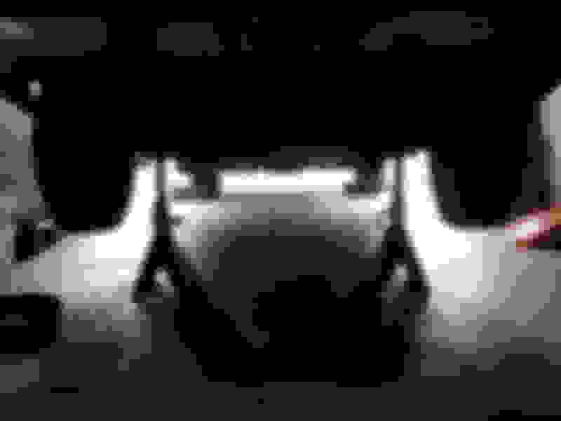
Now you are ready to remove the differential. You will not be able grab it and pull it out with your bare hands. Get a 3/4" box end wrench and place it on one of the ring gear bolts. Next, turn the pinion until the wrench contacts the top of the axle housing. Turn the pinion more and the differential will be forced out of the housing. Now is where you can grab it and remove it. If it is still tight, use a pry bar or other kind of lever.
With the differential removed, it is now time to remove the pinion and old pinion races, and install new races. You will need a long punch, hammer, pipe wrench & breaker bar or impact wrench, and a 1-1/4" socket.
I use the impact wrench along with the 1-1/4" socket to remove the pinion nut. I simply hold the yoke with one hand, and remove the nut with impact wrench. If you do not have air tools, the combination of the pipe wrench and breaker bar will get the job done.
Once the pinion nut is removed, you will need the long punch and hammer to remove the pinion from the housing. Thread the pinion nut a few turns just to keep the pinion from flying out of the housing. Place the long punch in the center of the pinion and hammer on it until it breaks loose.
Once the pinion is loose, remove the nut and yoke and finally the pinion.
With the long punch and hammer again, remove the pinion bearing races. You can actually remove the outer pinion race, out pinion bearing, and pinion seal in one shot.
There are grooves where the races seat. Locate these grooves to ease removal of the races.
To install the new races, use a race driver kit or a combination of a punch and the old races.
Now we address the pinion. Set-up bearings will be of great use here. To make these, get an old set of pinion bearings, a drill press, and 3/4" grinding stone from home depot. You will want to grind the ID of the bearings so that they are a slip fit on the pinion. Using set-up bearings relieves you from having to press on and press off the pinion bearings to make pinion shim adjustments.
Here I select my pinion shims and slide on the inner set-up bearing.
It is important that the correct shims are used to achieve proper pinion depth. A good starting shim is 0.035" for this particular axle.
1. With the shims and inner pinion bearing in place, slide the pinion into the housing.
2. Install the outer set-up bearing along with the yoke, washer and OLD pinion nut.
3. You will want to get the nut very tight to seat the bearings and shims on the pinion.
4. Back off the pinion nut until the pinion free spins about 1 turn when you spin it.
Now it is time for the new ring gear & differential assembly. Start by placing the assembly in the housing.
Determine your shim pack thicknesses using the old shims as a reference.
Now install the ring gear side shims.
Next, install the passenger side shims using a hammer and punch. These shims should not simply slide into place. They should be of sufficient thickness to where you have to hammer them into place with a punch. Also, you should not be able to grab the differential and pull it out with your bare hands once it is in place.
Reinstall the carrier bearing caps.
Installing the shims in the manner suggested insures that you will have the proper carrier bearing preload. This is important because the tighter you have the preload, the less chance you will have of the backlash opening up with the housing deflects under load.
Now we tackle backlash. This is important because too little backlash will over heat the gears while too much backlash will result in noise and possibly tooth breakage.
For this you will need the dial indicator and magnetic base. Set this up to where the point of the indicator is tangential to the ring gear.
Measure the backlash by moving ring gear back and forth. You will want 6-10 thousanths backlash for this axle. I like to aim for 7-8 thousanths.
If you have too much backlash, you will need to remove shims from the passenger side of the differential, and add the same amount to the ring gear side of the differential. If you have too little backlash, you will need remove shims from the ring gear side of the differential and add them to the passenger side. Again, the shims must fit tight.
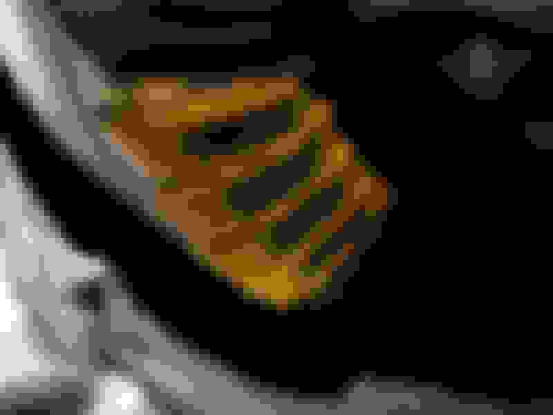
Once backlash is correct it is time to check for pinion depth. Mix the gear paint with some gear oil until you get a chocolate sauce consistency. Paint the coast side of the ring gear teeth as the coast side has more surface area to read the contact pattern from. Paint four teeth and run them back and forth across the pinion.
You will want the contact pattern to be centered between the root and crown of the gear teeth. Do not concern yourself with where the pattern is in regards to the heel and toe of the teeth.
Here is the resulting pattern:
Notice how the pattern is spread evenly between the root and crown of teeth. Despite the fact that the pattern in is more towards the heel of the tooth, this tells me that I have proper pinion depth and that this gear set will run quiet and problem free granted backlash, carrier bearing preload, and pinion bearing preload have been achieved and that proper break-in is done.
This step is where the Yukon Install Manual is handy because it shows you a number of correct and incorrect contact patterns. If the pattern you get is incorrect, you will need to take everything apart, adjust the pinion shims, reset backlash, and run the pattern again. Again, refer to the pictures in the Yukon Install Manual to determine whether your pattern is acceptable or unacceptable and adjust the pinion shims accordingly.
 04-03-2010, 05:10 PM