
Tips / Tricks / HowTo's
 04-11-2006, 09:20 PM
#1
TECH Senior Member
Thread Starter
iTrader: (1)
Join Date: Jan 2003
Location: Armpit of East TX
Posts: 9,342
Likes: 0
Received 0 Likes
on
0 Posts
If you have a good idea to get around some potentially difficult things you've encountered, post them up.
Start the post off with what it's referring to and follow the title up with a short but complete explanation of your tip or trick.
No post whoring, if you have a question about the matter, PM the user or start a new thread. If there are questions that should be included in the original post, please edit your original post, do not make a new post.
 04-11-2006, 09:24 PM
#2
TECH Senior Member
Thread Starter
iTrader: (1)
Join Date: Jan 2003
Location: Armpit of East TX
Posts: 9,342
Likes: 0
Received 0 Likes
on
0 Posts
Transmission Removal
Drop the transmission crossmember, supporting the trans with a jack. Raise the trans up with the jack still attatched to the engine as far as it will go without raising the truck. From the topside, you should be able to easily reach around the back of the intake and loosen the top nut/stud.
Go back under the truck, lower the trans with the jack to the point of it being as low as it will go, you should be able to reach all the remaining bolts from underneath with a 13 and 15mm socket, sometimes requiring a swivel on the end, and plenty of extensions to get you far enough back so that nothing is in the way.
04-11-2006, 09:41 PM
#3
TECH Senior Member
iTrader: (6)

Join Date: Jul 2005
Location: Decatur, AL
Posts: 5,257
Likes: 0
Received 0 Likes
on
0 Posts
Gen 3 Harmonic balancer install
Coat the inside & out of the balancer with a thin layer of grease. Take a propane torch and heat the inside of the snout for approx 60 seconds. Quickly install balancer (slip it on, it will bottom out very solidly). Hold for 10 seconds while it cools to prevent it from pushing back off. Tq new bolt to 37lbs then rotate 140* to stretch. Reheat as needed. Too much heat can melt seal so be careful! I recommend filling the wedge of the seal with grease as well.
People have had success with heating the entire balancer in the oven. The only problem I see is deteriorating the rubber damper sleeve that is in the middle of the balancer. Don't have any proof of damage though.
I have used the propane torch method many times with much success!
Some claim that reusing the old bolt and tqing it to 250 lbs with red locktite works as well. The new bolt is less than $5 from the dealer.
04-11-2006, 10:06 PM
#4
Tribe Shaman
iTrader: (4)

Join Date: May 2004
Location: Texas
Posts: 3,050
Likes: 0
Received 0 Likes
on
0 Posts
for those of you that do not have an air compressor and wish to change out your springs to handle a higher lift cam.
go to Walmart, home depot, or where ever and get some 5/16 rope.
with the piston all the way down in the cylinder feed in about 6 to 8 feet of rope through the spark plug hole.
turn the crank until the piston will not go up any more.
now with the rope filling the combustion chamber your valves have no where to go.
change out the springs on that cylinder, when you are finished just pull out the rope and move on to the next one.
04-16-2006, 12:02 PM
#5
TECH Addict

Cylinder Head Removal without removing the Intake Manifold:
If you don't want to bother removing the intake manifold and dealing with all of the electrical connections involved you can leave the intake on the motor and still remove both of the heads: Remove the intake piping, Loosen the 8 bolts holding the intake to the heads, remove passenger side PCV if so equipped, lift the intake away from the heads, Take 2 pieces of 2x4 about 8" long and slide them in between the valley cover and bottom of the intake making sure you don't damage the knock sensor wiring, Let the intake down onto the 2x4 pieces. The 2x4 pieces will give you just enough room to remove the heads without the intake interfering...the passenger-side head is the easier of the two to remove this way but with a little patience the drivers-side come off pretty easy too (you have to lift and slide the drivers-side head forward to clear the wiring harness and throttle cable)
If you don't want to bother removing the intake manifold and dealing with all of the electrical connections involved you can leave the intake on the motor and still remove both of the heads: Remove the intake piping, Loosen the 8 bolts holding the intake to the heads, remove passenger side PCV if so equipped, lift the intake away from the heads, Take 2 pieces of 2x4 about 8" long and slide them in between the valley cover and bottom of the intake making sure you don't damage the knock sensor wiring, Let the intake down onto the 2x4 pieces. The 2x4 pieces will give you just enough room to remove the heads without the intake interfering...the passenger-side head is the easier of the two to remove this way but with a little patience the drivers-side come off pretty easy too (you have to lift and slide the drivers-side head forward to clear the wiring harness and throttle cable)
04-16-2006, 04:40 PM
#6
TECH Regular
Official ENGINE R&R Guide
--------------------------------------------------------------------------------
This is a step-by-step removal and replacement of the 4.8, 5.3 and 6.0L trucks. I am not sure whether or not the deisel trucks are the same or not, I'm sure it's the same concept. This is intended to be a guide and I am not responsible if you get hurt or hurt anything on/in you truck while attempting to do this yourself. This should be performed by a trained and experianced mechanic. Ok, let's get started.
1. Loosen the hose clamps on both ends of the air tube assy and the hose clip on the passenger side of the radiator.
2. Next is the engine cover, 10mm nuts hold this on. Then the radiator shroud comes out when you take the 2 10mm bolts from the top of the shroud and the four pull-pins where the upper and lower part of the shroud connects.
3. Now put nuts/bolt in a tray/ziplock bag/muffin pan whatever you prefer but mark then accordingly.
4. Now the fan belt, use a 36mm wrench to twist the nut against the cranking rotation of the belt. Do not remove the belt before doing this, the belt will hold the water pump shaft in place while you loosen the fan nut. The fan but may be stuck so either have an air hammer or something else to accomodate.
5. Now drain the coolant, if you don't know how to do this you shouldn't be trying to pull the motor out in the first place.
6. Pull the the upper radiator hose on the engine off. The clamps will not slide on the hoses, just so you know.
7. Lower radiator hose and 2 heater hoses, Radiator hook may be needed here.
8. Remove the throttle cable, hold at WOT & unloop the cable. Remove the anchor as well, push the 2 tangs on the anchor and pull it out.
9. Upper cover bracket for the intake man, 3 10mm bolts hold it on.
10. Pull brake booster hose from the housing and start working on the ground straps. You'll have several, just look for them. I can't tell you everyone, someone else may can though.
11. Now starting on the Harness, TPS plug and altnator plug go next.
12. Now take the EVAP solenoid wire connectors and air temp senders. THese are located right behind the TB.
13. The mian wire harness clip needs to be unhooked, use a radiator tool.
14. Remove the coil plugs on both sides of the engines, you will have 8 total. When you get through with this, get the other altenatot wire, it's a 10mm.
15. Remove the Intake Manifold to get to the Knock sensor jumper wires unless you have it tagged or know it.
16. Fuel injector wiring harness, can be a bitch at first, just take your time and play with it a minute, it's hard to explain.
17. Now pull the water temp sensor wire on the driver's side of the block. Towards the front BTW.
18. Remove the MAP connector. It's on top of the intake towards the back.
19. Fuel lines, disconnect the to and from or feed and return lines. Do not lose the clips though. You'll need the special fuel line tool for this. be sure you have it.
20. Now we can take off the belt. Use the tensioner with a 15mm wrench.
21. Power steering pulley, take it off to see the bolts behind it. You will need a pully puller, go rent or buy one before you get started doing this.
22. Now take the 4 15mm Hex headed bolts out, 3 on the pump and 1 on the bracket. Keep up with bolts again.
23. Now zip-tie the PS pump to the inner fender well out of the way. It will stay there until we reinstall the engine.
24. AC, do the same with the AC compressor. 2 15mm Hex bolts on the side of the pump, and 2 on the bottom. Zip-tie it out of the way on the pass side.
25. Starter, 2 -13mm bolts and a 10mm bolt holding the flexplate access cover. You may have to play with it to get the starter out, time and patience my friend.
26. Now, while you're still under there, take the oil level connector off the oil pan and remove the 10mm bolt holding the harness on the fron of the oil pan.
27. Unbolt the exhaust collector. 3-15mm bolts hold it. Long extension needed or reccomended.
28. Remove 3 15mm bolts holding the flexplate and torque converter together. Use the hole you made with removeing the starter.
29. Remove all of the TRanny bolts you can, some are easier from the top, the top 2 anyway.
30. To get to the tranny bolts let's take the intake off. 10-8mm bolts hold the intake on and a few hoses and connectors. Clean around the itake before taking it off so you don't get **** in your ports.
31. Take the oil pressure sender and Knock sensors connector loose. May want to cover the ports at this time as well. Tape or shop towel whatever but do something.
32. Now disconnect the cam sensor connector and then remove the 10mm bolts hoding the brackets, about 3 I think. After this you'll be able to get to the other tranny bolts.
33. Now the motor mount bolts. 3-15mm bolts on each side, don't try to remove the engine until you take the loose.
34. Take the hood off now, if you haven't already. I would actuallly do it first but I am not changing it all now.
35. Start pulling, slowly and watching for anything you or me either one forgot. I'm sure I missed something so take your time and post up if know a different way/shortcut.
36. Start drinking your beer now. I wouldn't advise doing it until now though. lol. May tear something up.
Thanks for reading and if I can be of assistance please let me know.
Once again, a professional should at least be on hand while pewrforming this operation. Should you or anyone else get hurt I am not responsible. Should your vehicle get hurt or something go wrong I am not responsible. This is to be used as a guide only.
Have Fun with it.
2000_LS1
P.S. Be thankful you aren't doing it on a Camaro, Corvette or Firebird too. It's alot harder.
__________________
Hell...who knows what's next? 408 right now though.
EDIT THIS POST WAS MADE BY 2000 LS1. NOT BY MYSELF I JUST STUCK IT IN HERE.
Last edited by Flyer; 04-18-2006 at 06:24 PM.
The following users liked this post:
Vinnyv1967 (01-22-2021)
04-18-2006, 10:23 PM
#7

Dropping your engine and lining it up with the bellhousing
Since the flexplate is mounted onto the back of the motor and it can be kind of difficult to get the flexplate in the bellhousing while getting the motor mounts lined up with the frame the easiest way to get everything lined up is to put a floor jack under the transmission, and jack it up as high as it will go without crushing the pan. Then, drop the motor down into the truck and it should be much easier to get the flexplate in and the motor mounts where they need to be at the same time.
Since the flexplate is mounted onto the back of the motor and it can be kind of difficult to get the flexplate in the bellhousing while getting the motor mounts lined up with the frame the easiest way to get everything lined up is to put a floor jack under the transmission, and jack it up as high as it will go without crushing the pan. Then, drop the motor down into the truck and it should be much easier to get the flexplate in and the motor mounts where they need to be at the same time.
Trending Topics
04-22-2006, 02:57 AM
#8

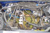
Avoiding Hood removal.
TIP...you DO NOT have to remove your hood to get the engine out. There are two sets of bolt holes where the springs attach to the hood. The ones closest to the front of the hood are where the springs normally attach, and the set further back is called the "service position". If you remove the bolts and reattach the springs to the rear holes, the hood will stand almost vertically, and will be out of the way. See attached pic.
TIP...you DO NOT have to remove your hood to get the engine out. There are two sets of bolt holes where the springs attach to the hood. The ones closest to the front of the hood are where the springs normally attach, and the set further back is called the "service position". If you remove the bolts and reattach the springs to the rear holes, the hood will stand almost vertically, and will be out of the way. See attached pic.
Last edited by Flyer; 04-26-2006 at 12:25 AM.
The following users liked this post:
Vinnyv1967 (01-22-2021)
04-25-2006, 09:32 PM
#9
Torque specs
Good link for just about any torque spec you can think of....(thanks for the link, quicksilverado )
)
http://www.ls1howto.com/index.php?category=1
Good link for just about any torque spec you can think of....(thanks for the link, quicksilverado
)http://www.ls1howto.com/index.php?category=1
Last edited by Flyer; 04-26-2006 at 12:24 AM.
06-26-2006, 09:03 PM
#10

Here is what is required to install an aftermarket intank pump in 99-02 return style sytems. The particular pump I used was a Holley #12-914 255LPH. Approx. install time 2.5~4 hrs.
Tools needed:
Small flat-blade screwdriver
Medium flat-blade screwdriver (or 8mm socket and ratchet for hose clamp)
Dremel tool or equivilant for bucket modification
Wire stripper/crimper, heat shrink and fuel hose
Wire ties
Carb cleaner
15 mm socket and long extension (I used a 3/8" ratchet)
Drill with 3/16" bit for holes to secure pump
1. Remove fill hose.
2. Support tank with suitable jack.
3. Remove the 2 strap bolts and straps.
4. Lower tank about 1 1/2 to 2 feet, or all the way down.(WATCH FUEL LINES).
5. Disconnect the 4 lines (3 on pump and 1 at rear of tank).
6. Disconnect the electrical connectors.
7. Jack vehicle enough to get tank out.
8. Remove pump module assy. (Just tap the Lock Ring to unlock it).
9. Unplug the sender and pump from the bottom side of Module.
10.Remove fuel bucket from module(1 clip on each side).
11.Unplug and remove pump (hose is a PITA but it will come off).
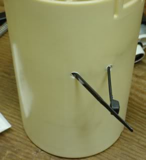
12.The bucket will have to be modified at the bottom so the pump inlet will go through the bottom far enough to install the filter sock. (I used a dremel tool) see pic #1 below.
13.Then I had to modify the bucket so i could secure the pump. See pics 2 & 3 below.
14.Next you will have to splice the new connector onto your harness. I cut them at different lengths, heat shrinked and also slid a piece of hose over each splice to insure they couldn't touch if the heat shrink didn't hold up.
15.Now plug the new pump in, and install the hose and clamp.
16.I went ahead and routed the zip-tie through the bucket before dropping the pump in.
17.Now drop the module and pump back into the bucket, making sure to clip both clips on the bucket.
18.Insure that the pump is all the way down and secure it using a zip-tie already installed in step 16. You can also install the filter sock now.
19.Reinstall the pump assy. into tank and secure with lock ring.
20.Slide tank under truck and reconnect the 4 lines and 2 electrical connectors.
21.Reinstall tank (2 straps and filler tube).
I'm sure I may of left something out but I think that this pretty well covers the install procedure. The pics are from Ranwalk's older thread because I forgot to take pics while I had it apart. These are the pictures I used for a guide.
Pic 1

Pic 2

Pic 3
Tools needed:
Small flat-blade screwdriver
Medium flat-blade screwdriver (or 8mm socket and ratchet for hose clamp)
Dremel tool or equivilant for bucket modification
Wire stripper/crimper, heat shrink and fuel hose
Wire ties
Carb cleaner
15 mm socket and long extension (I used a 3/8" ratchet)
Drill with 3/16" bit for holes to secure pump
1. Remove fill hose.
2. Support tank with suitable jack.
3. Remove the 2 strap bolts and straps.
4. Lower tank about 1 1/2 to 2 feet, or all the way down.(WATCH FUEL LINES).
5. Disconnect the 4 lines (3 on pump and 1 at rear of tank).
6. Disconnect the electrical connectors.
7. Jack vehicle enough to get tank out.
8. Remove pump module assy. (Just tap the Lock Ring to unlock it).
9. Unplug the sender and pump from the bottom side of Module.
10.Remove fuel bucket from module(1 clip on each side).
11.Unplug and remove pump (hose is a PITA but it will come off).
12.The bucket will have to be modified at the bottom so the pump inlet will go through the bottom far enough to install the filter sock. (I used a dremel tool) see pic #1 below.
13.Then I had to modify the bucket so i could secure the pump. See pics 2 & 3 below.
14.Next you will have to splice the new connector onto your harness. I cut them at different lengths, heat shrinked and also slid a piece of hose over each splice to insure they couldn't touch if the heat shrink didn't hold up.
15.Now plug the new pump in, and install the hose and clamp.
16.I went ahead and routed the zip-tie through the bucket before dropping the pump in.
17.Now drop the module and pump back into the bucket, making sure to clip both clips on the bucket.
18.Insure that the pump is all the way down and secure it using a zip-tie already installed in step 16. You can also install the filter sock now.
19.Reinstall the pump assy. into tank and secure with lock ring.
20.Slide tank under truck and reconnect the 4 lines and 2 electrical connectors.
21.Reinstall tank (2 straps and filler tube).
I'm sure I may of left something out but I think that this pretty well covers the install procedure. The pics are from Ranwalk's older thread because I forgot to take pics while I had it apart. These are the pictures I used for a guide.
Pic 1
Pic 2
Pic 3