
Checked out the heads today
 11-01-2010, 10:16 PM
#71
Did some more number crunching and the "B" dimension appears to be adequate on paper anyway. Can't get a visual confirmation with the springs/dampers fully compressed.
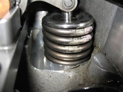
I'm thinking that maybe the spring seats were bouncing because they hit the bottom edge of the seals if you lift them. The way some of the seals are rolled on both ends looks like they were getting hammered back and forth between the spring seats and spring retainers.
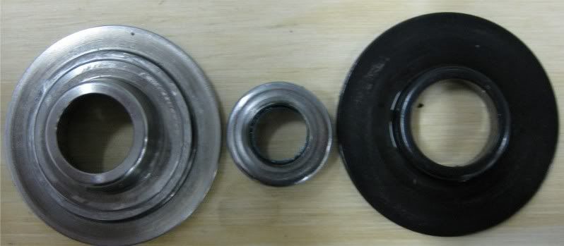
I'm thinking that maybe the spring seats were bouncing because they hit the bottom edge of the seals if you lift them. The way some of the seals are rolled on both ends looks like they were getting hammered back and forth between the spring seats and spring retainers.
Last edited by DrX; 11-01-2010 at 10:33 PM.
 11-02-2010, 12:29 AM
#72

That's what I was talking about when I said it looked like the springs weren't up to the task. We still don't know anything about the springs, except that they are dual springs. Just a little bit of looking around at different spring sets, the "advertised" spring pressures don't even seem adequate for your build. Hopefully your heads aren't trashed.
11-02-2010, 12:04 PM
#73
The heads look OK. Can the bottom of the springs actually lift off the pocket base like that?
What kind of seat and open pressures would be suited for running 20 psi and shifting at 6500 RPM? Including a decent safety margin.
This is interesting(from Magnum Powers site):
Introduction:
Some have theorized intake valves in supercharged engines require greater seat pressure (valve closed) then naturally aspirated (NA) engines therefore stronger valve springs are required. This article discusses a theory regarding valve spring requirements and documents dyno results as realized in the supercharged Ford F150 Lightning.
Valve Spring Requirement:
Valve springs return the valve head to its seat after being opened by the cam and holds the valve head against the seat until the camshaft opens the valve again on the next cycle. The valve spring needs to be strong enough to overcome the inertia of the valve train so the valve follows the contour of the camshaft for proper valve action. As RPM increases the inertia increases at the square of rpm requiring much stronger valve springs in high RPM engines. The Valve Train in a push rod engine consists of the valve, valve spring, lifter, push rod and rocker arm. In an overhead cam engine only the valve, valve spring and cam follower are involved. Since there is less mass to overcome in an overhead cam engine the valve springs can be weaker. Engines manufacturers typically install the weakest valve spring possible that will properly close the valve throughout the desired RPM range of the engine. Engine manufacturers use valve spring strength to limit valvetrain wear and useful RPM power band thus designing in a RPM governor all of which improves reliability.
Additional Valve Spring Requirements:
There are two distinct additional requirements a supercharged engine places on valve springs. These requirements are not recognized by leading valve spring manufacturers or most race engine builders and are therefore a new concept to most people looking for increased performance. Firstly supercharged engines require stronger valve springs then NA engines do to a force applied to the valve head that is associated with manifold pressure and the engine�s volumetric efficiency (VE). If for instance a supercharged engine running 20-psi manifold pressure has a volumetric efficiency of 100% when the piston reaches the bottom of the intake stroke and the intake valve closes there will be 20-psi on both sides of the valve head, i.e., 20-psi on the intake manifold side and 20-psi on the cylinder side because the cylinder fully filled with air during the intake cycle. Since the air pressure in this case are the same on both sides of the valve no force is applied to the valve head. If however the engine has a volumetric efficiency of only 50% there will be 20-psi pressure on the manifold side but only 10-psi on the cylinder side when the valve closes, because the cylinder did not completely fill, a net pressure of 10-psi will be present across the valve head. If the intake valve has a surface area of 2.5 square inches a force of 25 pounds (2.5x10) will be generated that will be trying to open the valve thus reducing the effective valve spring pressure by 25 pounds. Since engine manufacturers install valve springs that are only strong enough to support proper valve action to their RPM limit any reduction in effective valve spring strength will lower the useful power band RPM limit. If the valve spring does not have enough strength to keep the valve following the camshaft profile the valve is said to �float�.
The second additional requirement arises during the exhaust cycle. During the exhaust cycle the cylinder pressure drops to zero or can even go negative do to exhaust header-savaging effects. During the exhaust cycle the intake valve spring must be strong enough to hold the intake valve closed against manifold pressure. If the manifold pressure is 20-psi and the valve head has 2.5 square inches of surface area the force attempting to open the valve will be 50 pounds (2.5x20). If the intake valve opens during the exhaust cycle the air/fuel intake charge will flow through the intake valve and out the exhaust valve during the exhaust cycle and will not be used by the engine to develop power.
The Ford F150 Lightning SVT Experience:
As Lightning owners began modify their Lightning by increasing boost pressure some did not realize the expected performance increases. Most noticeable were upgrades to the Magnum Powers supercharger that are capable of 25-psi boost. Rob Caruso who attempted to run 24-psi boost on his Lightning with stock heads chronicled his experience on one of the Lightning bulletin boards, the result were disastrous. Prompted by Rob�s experience Magnum Powers initiated an investigation to determine the reason for poor power, weak valve springs was identified as the cause.
As it turns out Ford used the same valve springs in the Supercharged F150 5.4L Lightning SVT as in all other 2-Valve Modular motors including the 4.6L and 5.4L engines. The most likely reason Ford used standard valve springs is because the Lightning�s performance as outfitted from the factory met Ford�s Marketing requirements and also for commonality of parts. Unfortunately the valve springs are not strong enough to support optimum performance at boost pressures greater then stock.
Valve Spring Theory Proven by Test Results:
A plate was fabricated and bolted across the intake port in place of the intake manifold at Magnum Powers� laboratory and then the intake port was pressurized to simulate boost pressure. Air pressure was increased slowly until at 18-psi the valve opened and air started leaking past the valve seat revealing for the first time, by testing, that the Lightning�s valve spring pressure is inadequate. These tests were later collaborated by others within the Lightning community. As air pressure as increased further air leakage pass the valve seat became very significant on the order of 5-10cfm.
At this point Magnum Powers requested dyno tests be conducted at Fast Specialties of Vancouver Washington (http://www.fastspecialties.com/) to determine if stronger valve springs would yield improved performance. The vehicle selected was a Lightning that had aftermarket 80-pound valve springs measured when the valve is closed (VC) a dyno pull was conducted and that dyno chart was used for the baseline. Next the Lightning�s valve springs were upgraded to Manley 95-pound (VC) springs and the tests repeated. The results showed a 17 hp gain at 5,200 rpm at 15-psi boost and a 30hp gain at 18-psi boost. Since the Lightning�s stock springs are only about 70-pounds (VC) when new and less when used the improvement would have been greater if stock springs were used for the baseline.
Jim D�Amore of JDM (http://www.teamjdm.com/) began his own series of tests that involved spring pressures of 105-pounds (VC) resulting in additional power increases. Jim has reported indications stronger springs then 105 pounds are required for maximum performance therefore at this time JDM is working with one of their suppliers to develop a 120-pound valve spring for the Lightning that will soon be available.
Below is a dyno chart of a Lightning with stock valve springs. Notice how the HP curve peaks at about 4700 RPM (where the valves begins to float) and then power begins to decrease. This chart is characteristic of Lightnings with stock valve springs running high boost. Because stock 5.4L engines have low volumetric efficiency at higher RPM there is a significant reduction of effective valve spring pressure do to the differential pressure across the valve head causing the valves to float at a relatively low RPM if operating at high boost levels.
 A dyno chart of a different engine is shown below. This engine was outfitted with 80-pound (VC) springs and a dyno pull made and then the valve springs were exchanged for 95-pound (VC) springs. Notice that power peaked at 4,800 RPM with the 80-pound springs but when the valve springs were replaced with 95-pound springs power peaked at around 5,100 RPM.
 After Rob Caruso�s great disappointment of attempting to run high boost with stock valve springs his engine was replaced with a JDM long block with 105-pound valve springs and equipped with the Magnum Power supercharger case. Notice how the engine pulls very strong and power peaked around 5,400 RPM (top curve). When boost was lowered two-psi peak power occurred at 5,800 RPM (lower curve) demonstrating 105-pound valve springs are not strong enough for maximum performance and hence JDM�s started a project to develop 120-pound valve springs for the Lightning.
 Magnum Powers has designed valve spring tools that enables the valve springs to be replaced with the engine still in the truck in just a few hours. Click here for details and/or call Magnum Powers.
LATEST NEWS: Newly designed JDM/Manley springs are now available, spec'ed at 125 pounds on the seat and good for .550" lift. You can purchase these springs through Magnum Powers. For $150 deposit we will loan the tools to you for one month if you purchase the valve springs through us.
11-02-2010, 07:36 PM
#74
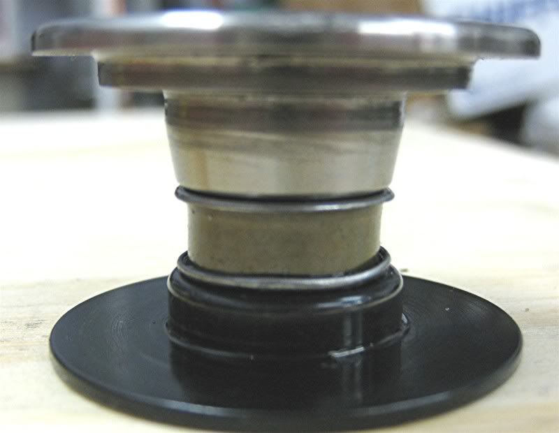
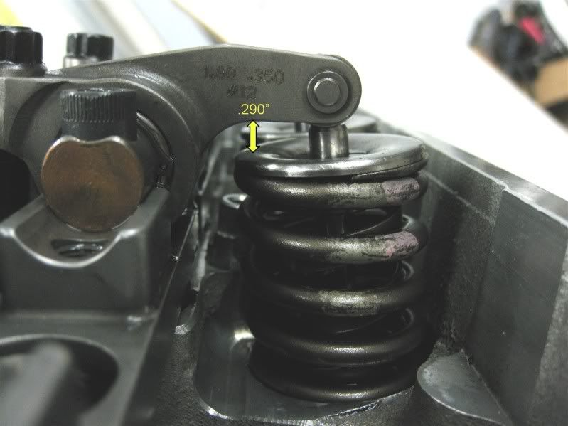
Not second guessing you or you builder, but it would appear to me from the pictures you have taken that you have plenty of valve stem length to run a taller installed height valve spring package than your currently using and could alleviate some of your coil bind and clearance issues all without changing your valve-train geometry. As it is, you have quite a bit of valve stem above the retainer and locks, more so than what you need for rocker arm clearance. Of course the rocker to retainer clearance will need to be checked with the valve closed and not open as in the picture.
Last edited by 1Bear; 11-02-2010 at 07:41 PM.
11-02-2010, 09:11 PM
#75
Not second guessing you or you builder, but it would appear to me from the pictures you have taken that you have plenty of valve stem length to run a taller installed height valve spring package than your currently using and could alleviate some of your coil bind and clearance issues all without changing your valve-train geometry. As it is, you have quite a bit of valve stem above the retainer and locks, more so than what you need for rocker arm clearance. Of course the rocker to retainer clearance will need to be checked with the valve closed and not open as in the picture.
 11-02-2010, 11:51 PM
#78
Good thread to read, guys. Unfortunately DrX had to suffer in order for us to learn.
Maybe you should try measuring the clearance by putting some modeling clay around the top of that valvestem seal and then assembling the valve. Rotate the engine, disassemble the valve components and measure the thickness of the clay.
Maybe you should try measuring the clearance by putting some modeling clay around the top of that valvestem seal and then assembling the valve. Rotate the engine, disassemble the valve components and measure the thickness of the clay.
 11-03-2010, 11:53 AM
#80
On The Tree

Join Date: Oct 2010
Location: SOUTHERN NEW JERSEY
Posts: 147
Likes: 0
Received 0 Likes
on
0 Posts
yes fellas a do agree.it is a damn shame for us to learn like this at this gentlemens expense. im more familiar with building big block modified engines and sprint engines.so,some of the new technology that im seeing on this site,to me is pretty cool.not to mention the engine this dude is running.the cubes then on top of it the induction system. WOW !!!! its definately a radicle set up,theres a tremendous amount of things happeing inside the engine that alot of people over look when putting the normally aspirated engine together. honestly i cant wait for it to be running again and he POSTS a video of the vehicle running the quarter mile. if those tire grab,the time slip should be AWESOME !!! also hope i never pull up next to hom at a red light thinkin"lets run'em".