My new powerplant (408 with a healthy direct port shot)
 08-19-2008, 04:01 PM
#51

Thanks for the comps guys,...this build certainly isn't a quick bolt in and go as it gets frustrating sometimes having all of the little roadblocks to deal with but it is sure rewarding.
I will most likely just grab some 4" Al tube and some silicone couplers and mate it up to the existing Volant box.
What I was thinking is that I may come off the TB with 4", get creative with the welder and do a split and curve 2 large red filters down to the opening in the SS bumper. I will polish the Al tubing and have it annodized red. My only concern is the heat it will suck in. It will look badass but not too performance oriented. I may do it just for show and have another one for track days.
I am trusting that the LS6 valley cover will really help with oil control and pressure (posted some pics earlier on the comparo of the stock vs. the LS6). I really don't think I will have too much of an issue using a vette PCV and a small catch can as well as the LS6 valley cover.
Yep picture is correct. The bung is on the last 2 cylinders only (5,6,7,8). The wideband will be in the true collector.
What I was thinking is that I may come off the TB with 4", get creative with the welder and do a split and curve 2 large red filters down to the opening in the SS bumper. I will polish the Al tubing and have it annodized red. My only concern is the heat it will suck in. It will look badass but not too performance oriented. I may do it just for show and have another one for track days.
On those tri-Y headers did I see the O2 bung welded just to the rear collector or does the picture not show a second O2 bung on the other side? Usually O2's are set up downstream from the main collector so I'm just wondering if those tri-Y's are set up to monitor just the rear 4 cylinders or all 8.

 08-27-2008, 02:41 PM
#54
TECH Fanatic
iTrader: (24)

Join Date: Dec 2004
Location: Houston, TX
Posts: 1,825
Likes: 0
Received 0 Likes
on
0 Posts
Intake idea sounds similar to the one I'll be building with a friend soon. It will definitely heatsoak like a bitch, but if you got it ceramic coated on the inside/outside it wouldn't be bad. Fiberglass heat wrap does wonders, but wouldn't go well with your uber-clean engine bay.
09-19-2008, 04:00 PM
#55
Quick update...I had a ton of great pictures however I am having a major issue with my one SD card. Anyway, here is an update on my build consisting of:
1. PCV / crankcase venting / oil control.
2. Intake finally officially mounted
3. Catch Can install
4. CAI home brew
First off, I received a ton of PM's and E-mails on how I was going to do a PCV and crankcase venting set-up so I figured I would detail this here. A correct and correctly engineered crankcase venting system will consist of 3 basic aspects:
1. Adequate venting of crankcase pressure. I think it is safe to say all motors have some form of blow-by and for the high rev'ing or boosted applications, this can be a big concern if not adequately vented.
2. A fresh air source to effectively flush / scavenge the crankcase of harmful gasses. Venting the crankcase is only half. Your motor will create a nasty mixture of gasses in your crankcase including water vapor, oil vapor, unburnt and burnt fuel vapor and acids which will cause damage to your internal engine components if allowed to condense back. A well designed system will have a fresh air source AND a vacuum source to effectively pull these gasses out of the system.
3. A method by which you can remove oil vapor from the crankcase. AKA a catch can! These should come as a factory installed option IMO. A good catch can will regulate the amount of air flowing through it, have some method of allowing the hot vapors to condense and separate and also a good design so that maximum condensing can be achieved.
So with that being said, here is what I did and why. I first did some research on catch cans and made my choice based on functionality, looks and finally price. It came down to the AMW piece or the CCA can. I ended up buying the CCA due to design and the way I was going to route my vac lines. I did have an exploded picture for you so that you can see all the internal parts however that is stuck in my corrupt SD card. I mounted the can on the passenger head.
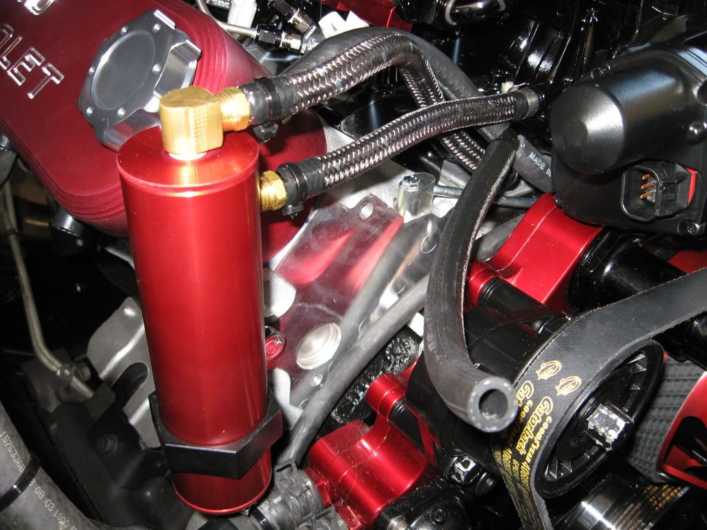
Everybody remembers that I installed the LS6 valley cover correct? Well this is why... I am going to pull crankcase pressure and gasses from the valley cover instead of the valve covers. The outlet of the LS6 Valley cover is connected to the TOP inlet of my catch can which travels through a cylinder containing mesh fiber inducing the condensation of the oil vapors. The large body of the catch can also aids in the condensation before traveling up and out the top side of the can into my vacuum source in the FAST intake. The LS6 Valley cover alone has properties that will help control the oil vapor (look back a few pages to the pictures).
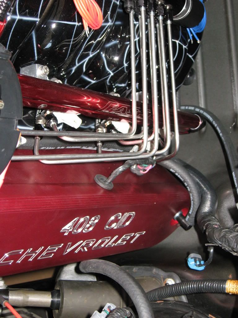
O.K. now that I have the crankcase pressure taken care of I needed to satisify a fresh air source and plumb the lines to the crankcase. I wanted to have this fresh air source come in from the TOP of both valve covers, make its way down the push rod voids and finally "sucked up through" the LS6 valley cover. I felt that will give me the best overall "flush" of the motor. Now, for my set-up I will initially be using the MAF sensor which means I cannot just add "breathers" to the valve covers as the motor will "see" UNMETERED AIR and mess with my fuel trims. Yes, I know you can effectively "tune out" this intentional leak but I refuse to believe that it will be a consistant intentional leak. Solution I chose is to tap into the CAI tube after the MAF sensor split and route vacuum lines to the valve covers. Here is the bung I installed in the intake tube:
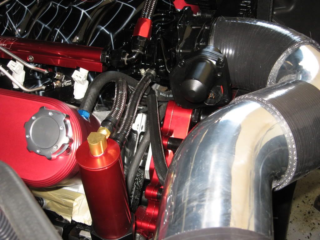
This fresh air source will be effective at idle and part throttle only as when I go WOT, both the vacuum source for the catch can and the fresh air source will see relatively the same vacuum reading. I went one step further and enlarged the stock pinhole "PCV" to about double the size allowing better airflow through the top of the driver's side. Again, I had nice pictures of this. Here is just a finished pic of where the vacuum line will be run (pay no attention to how dirty and how the wiring is all over the place, this is a BUILD thread, not a final PIC thread ):
):
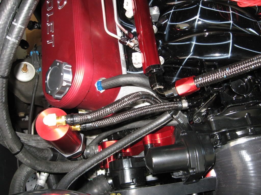
Here is a good look at the vacuum lines split in various directions. I will dress all of the lines up with nice black hose clamps and such however I am getting anxious and the bank account is GONE!:
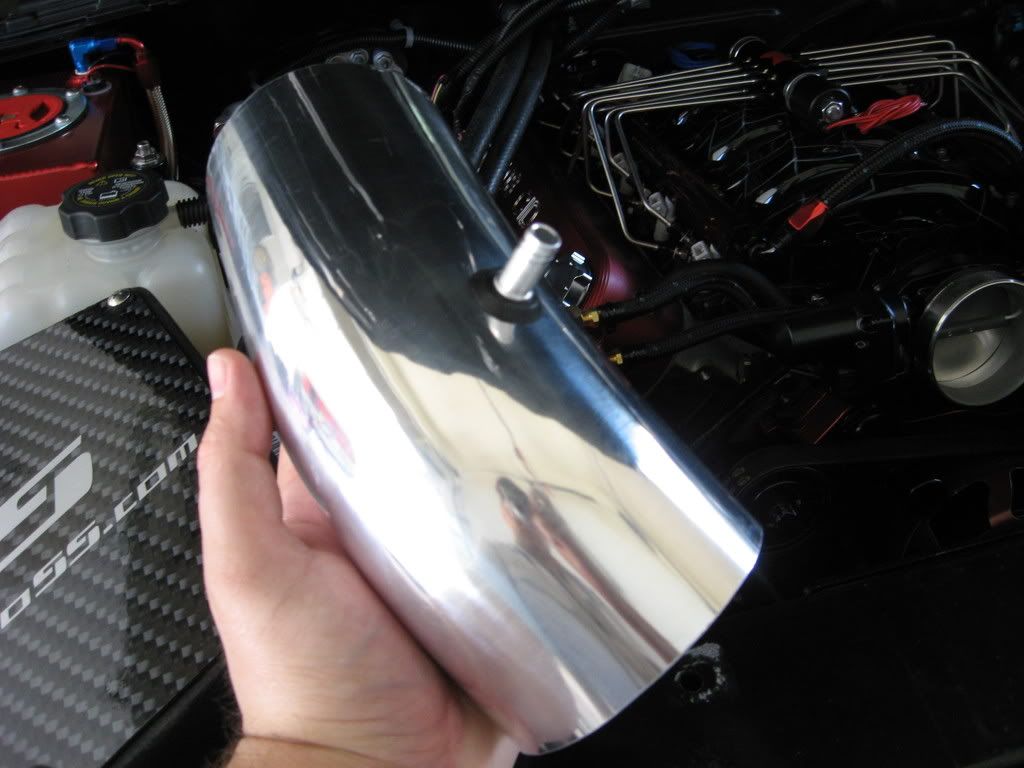
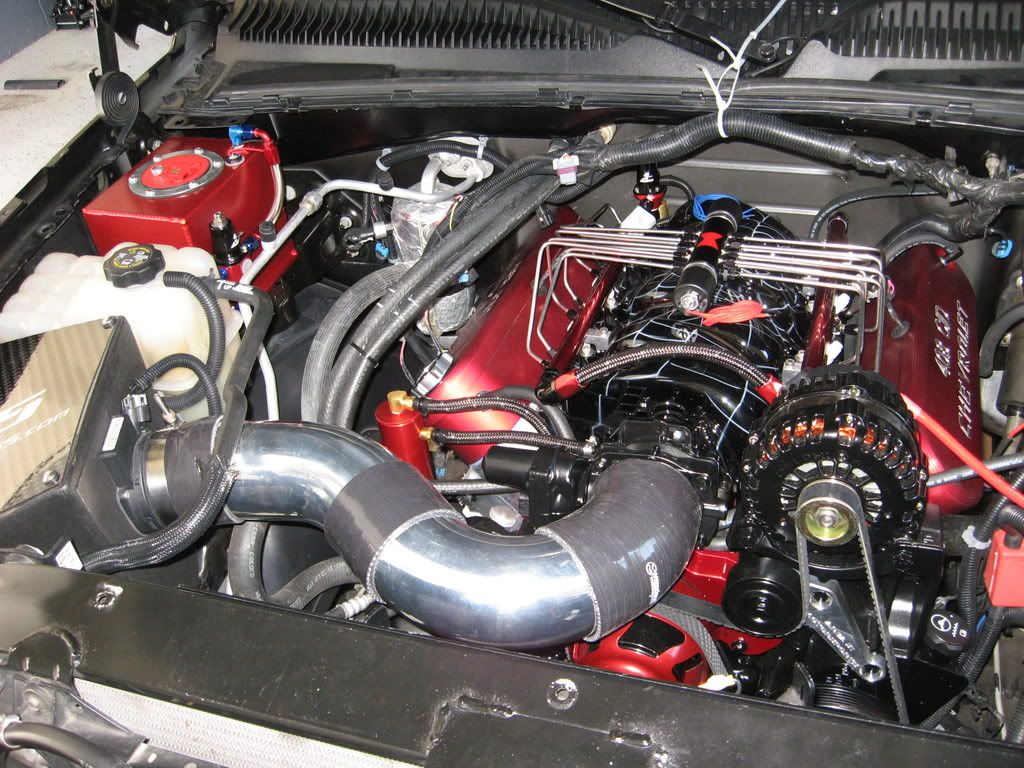
A look with the CAI mocked up. I will be powdercoating the intake tubing black for less "bling" as well.
Overall so far. I still need to officially bolt down the coil covers and finish up the wiring so pay no attention to the details ...YET. Anyway, the CAI is home brew and consists of a 4" 45* silicone coupler, a 90* 4" bend of aluminum with one 2 inch leg and one 3 inch leg, a 4 inch silicone coupler, a 45* 4" aluminum bend with 2 inch legs and a 4 inch leg and finally a 4 inch to 3.8 inch silicone reducer. I will one day make a trick intake, splitting the pipe right off the TB goinng to the lower grill. But that is a ways away for now...
1. PCV / crankcase venting / oil control.
2. Intake finally officially mounted
3. Catch Can install
4. CAI home brew
First off, I received a ton of PM's and E-mails on how I was going to do a PCV and crankcase venting set-up so I figured I would detail this here. A correct and correctly engineered crankcase venting system will consist of 3 basic aspects:
1. Adequate venting of crankcase pressure. I think it is safe to say all motors have some form of blow-by and for the high rev'ing or boosted applications, this can be a big concern if not adequately vented.
2. A fresh air source to effectively flush / scavenge the crankcase of harmful gasses. Venting the crankcase is only half. Your motor will create a nasty mixture of gasses in your crankcase including water vapor, oil vapor, unburnt and burnt fuel vapor and acids which will cause damage to your internal engine components if allowed to condense back. A well designed system will have a fresh air source AND a vacuum source to effectively pull these gasses out of the system.
3. A method by which you can remove oil vapor from the crankcase. AKA a catch can! These should come as a factory installed option IMO. A good catch can will regulate the amount of air flowing through it, have some method of allowing the hot vapors to condense and separate and also a good design so that maximum condensing can be achieved.
So with that being said, here is what I did and why. I first did some research on catch cans and made my choice based on functionality, looks and finally price. It came down to the AMW piece or the CCA can. I ended up buying the CCA due to design and the way I was going to route my vac lines. I did have an exploded picture for you so that you can see all the internal parts however that is stuck in my corrupt SD card. I mounted the can on the passenger head.
Everybody remembers that I installed the LS6 valley cover correct? Well this is why... I am going to pull crankcase pressure and gasses from the valley cover instead of the valve covers. The outlet of the LS6 Valley cover is connected to the TOP inlet of my catch can which travels through a cylinder containing mesh fiber inducing the condensation of the oil vapors. The large body of the catch can also aids in the condensation before traveling up and out the top side of the can into my vacuum source in the FAST intake. The LS6 Valley cover alone has properties that will help control the oil vapor (look back a few pages to the pictures).
O.K. now that I have the crankcase pressure taken care of I needed to satisify a fresh air source and plumb the lines to the crankcase. I wanted to have this fresh air source come in from the TOP of both valve covers, make its way down the push rod voids and finally "sucked up through" the LS6 valley cover. I felt that will give me the best overall "flush" of the motor. Now, for my set-up I will initially be using the MAF sensor which means I cannot just add "breathers" to the valve covers as the motor will "see" UNMETERED AIR and mess with my fuel trims. Yes, I know you can effectively "tune out" this intentional leak but I refuse to believe that it will be a consistant intentional leak. Solution I chose is to tap into the CAI tube after the MAF sensor split and route vacuum lines to the valve covers. Here is the bung I installed in the intake tube:
This fresh air source will be effective at idle and part throttle only as when I go WOT, both the vacuum source for the catch can and the fresh air source will see relatively the same vacuum reading. I went one step further and enlarged the stock pinhole "PCV" to about double the size allowing better airflow through the top of the driver's side. Again, I had nice pictures of this. Here is just a finished pic of where the vacuum line will be run (pay no attention to how dirty and how the wiring is all over the place, this is a BUILD thread, not a final PIC thread
):Here is a good look at the vacuum lines split in various directions. I will dress all of the lines up with nice black hose clamps and such however I am getting anxious and the bank account is GONE!:
A look with the CAI mocked up. I will be powdercoating the intake tubing black for less "bling" as well.
Overall so far. I still need to officially bolt down the coil covers and finish up the wiring so pay no attention to the details ...YET. Anyway, the CAI is home brew and consists of a 4" 45* silicone coupler, a 90* 4" bend of aluminum with one 2 inch leg and one 3 inch leg, a 4 inch silicone coupler, a 45* 4" aluminum bend with 2 inch legs and a 4 inch leg and finally a 4 inch to 3.8 inch silicone reducer. I will one day make a trick intake, splitting the pipe right off the TB goinng to the lower grill. But that is a ways away for now...