IAT Bias Issue?
#21
Thread Starter
TECH Senior Member
iTrader: (7)
Joined: Jun 2004
Posts: 5,446
Likes: 7
From: Central Kentucky
^^^^ Wow. You have too much time on your hands 
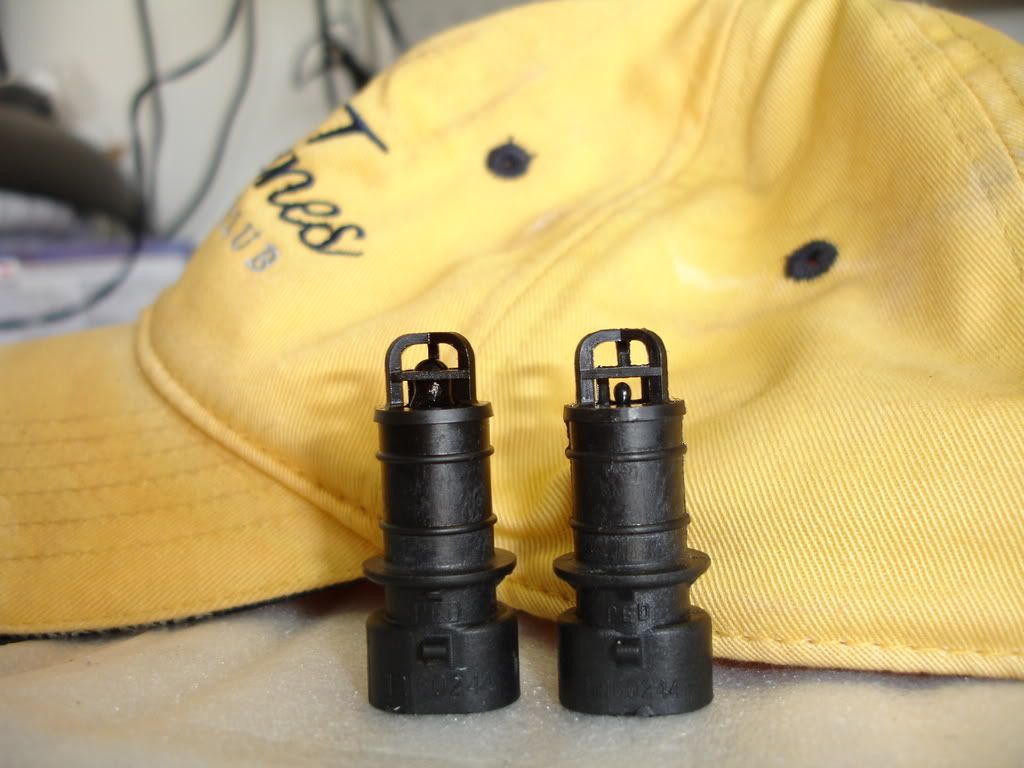
I'll post pics of mine when I get it modded up. Basically the stock IAT for the maggie and the wiz bang super fast responding Omega sensor soldered in. Found the sensor today. Ripped a couple fingers up nicely pulling the sensor plug out of it.
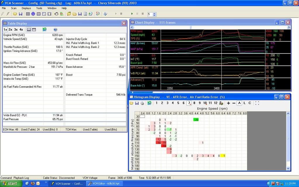
Anywho did the most tuning and logging tonight since getting the 60# Mototrons in. Capped the evening with a full pull through 1st. It's nice to see no knock... no methanol. 20.5 timing through 1st gear. It shift at its setpoint like its SUPPOSE to and only 64% duty cycle. In the majority of cruise spots the VE is good. I'm going to be pissed when I log it again and its all to hell.


#22
Found a good write up on the omega sensor.
http://kb.ls1gto.com/KB/article.aspx?id=10279
I'll try it but I am skeptical. Two things come to mind. 1> The sensor is encased in plastic. Plastic is a very good insulator. 2> This unit responds quicker but the time that I drove should have allowed for the sensor or charger cool down. It didn't.
http://kb.ls1gto.com/KB/article.aspx?id=10279
I'll try it but I am skeptical. Two things come to mind. 1> The sensor is encased in plastic. Plastic is a very good insulator. 2> This unit responds quicker but the time that I drove should have allowed for the sensor or charger cool down. It didn't.
MAF'd tunes don't really need to worry about this so much, as the incoming air charge is still being metered and not calculated entirely based on conditions.
The stock bias table was set-up with the iat sensor in the maf no-where near the engine coolent, although under hoot temps still apply SOME WHAT. Which is why the factory bias so much toward air temp. The radix intake being aluminum and mounted right on top of the engine would defenitealy warrant a bias more toward the ect. how much? who knows. like others have said 1 seams to be the magic number.
#23
How do I change this text
iTrader: (26)
Joined: Jan 2005
Posts: 7,294
Likes: 2
From: Behind the TIG welder
I would suggest the opposite of this based on data from multiple tests. If the IAT sensor were located in the MAF, then by all means, bias heavily toward ECT. But since the sensor is threaded into the upper intake manifold, you've really only got 6-8 inches of movement from the measurement location til the combustion chamber. At low flow, the bias would be worth exploring, but the headache associated with doing so may not be worth the effort. I'll fire this up a bit tomorrow to see what type of results can be had.
#24
Because of the IAT's location within the radix, GM's design is thrown completely out the window. With the IAT sensor as close as it is to the combustion chamber, the air charge does not have much time to be heated up. Combine that with the very visible heat soak issue due to the IAT sensor being mounted so close to the wall of the radix upper manifold and things get more complicated than a simple equation can account for.
#25
Hence just turning it off IMO.
I think you could crutch it with bias, but there is just to many holes for it. Maybe if you had a third temperature to use as a bias, like blower temp or something. The calculation doesn't have anything to take heat soak into effect. As far as IAT sensor as close as it is to the combustion chamber, the air charge doesn't have time to be heated up...I believe you could use GM's calc to adjust for that. But could care less because I can't get rid of heat soak.
I think you could crutch it with bias, but there is just to many holes for it. Maybe if you had a third temperature to use as a bias, like blower temp or something. The calculation doesn't have anything to take heat soak into effect. As far as IAT sensor as close as it is to the combustion chamber, the air charge doesn't have time to be heated up...I believe you could use GM's calc to adjust for that. But could care less because I can't get rid of heat soak.
#26
How do I change this text
iTrader: (26)
Joined: Jan 2005
Posts: 7,294
Likes: 2
From: Behind the TIG welder
Because of the IAT's location within the radix, GM's design is thrown completely out the window. With the IAT sensor as close as it is to the combustion chamber, the air charge does not have much time to be heated up. Combine that with the very visible heat soak issue due to the IAT sensor being mounted so close to the wall of the radix upper manifold and things get more complicated than a simple equation can account for.
That is why I would think you would want to bias more toward ECT at the lower air flow scale..... I kinda look at "ECT" as heat soak, maybe that is why I'm backwards....?
One thing we all agree on, we need more control over the air density calculations in S/D.

#27
Here's an example.
Warm restart, ECT temp = 190, IAT temp reading = 120, actual charge temp = 95
bias disabled, the PCM's charge temp calculation would be 120*, 25* higher than actual, causing a moderate lean condition.
With a bias of .5, the PCM's charge temp would be 155*, 60* higher than actual, causing a much more significant lean condition.
Bias even further towards ECT and you'd lean out even further.
#28
How do I change this text
iTrader: (26)
Joined: Jan 2005
Posts: 7,294
Likes: 2
From: Behind the TIG welder
That would exacerbate the problem...
Here's an example.
Warm restart, ECT temp = 190, IAT temp reading = 120, actual charge temp = 95
bias disabled, the PCM's charge temp calculation would be 120*, 25* higher than actual, causing a moderate lean condition.
With a bias of .5, the PCM's charge temp would be 155*, 60* higher than actual, causing a much more significant lean condition.
Bias even further towards ECT and you'd lean out even further.
#29
Thread Starter
TECH Senior Member
iTrader: (7)
Joined: Jun 2004
Posts: 5,446
Likes: 7
From: Central Kentucky
Modded my IAT today. Haven't driven yet. 2 worries. 1> The Omega bulb is a dainty thing and the cage around the senor will not stop it if it should break off. Don't think it would hurt anything though. 2> I just verified it was reading. First startup IAT reading 84F the mirror thermo showed 93F.
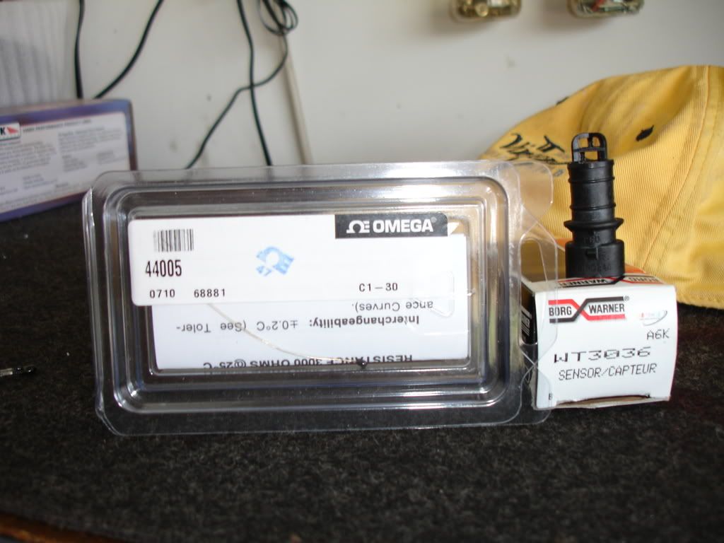
Part numbers for anybody that may be interested.
Omega 40005
IAT sensor for a 98 Camaro. 5.7L - Borg Warner - WT3036. Not necessary if you want to mod the one on a maggie. They are the same. I like to have backups incase I screw it up.

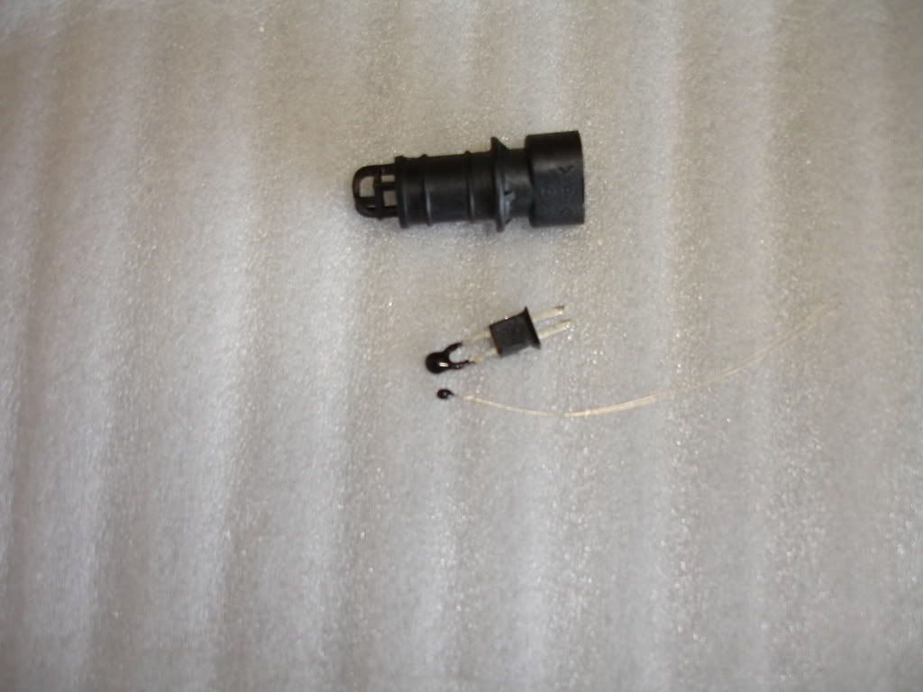
A good pair of needle nose pliers on the sensor terminals and you can pull it out of the unit. Here is a picture of it removed and the Omega in there for reference. I can see how the omega responds quicker. Its much smaller.

Then its just a matter of snipping off the stock sensor and soldering on the Omega unit. Then pushing it back in the casing. Took a bit love with hammer and punch to get it seated all the way. I made a reference mark on a piece of paper to get the length right when soldering on the new sensor. I didn't want it sticking way out into the cage because of the flimsy leads.

Part numbers for anybody that may be interested.
Omega 40005
IAT sensor for a 98 Camaro. 5.7L - Borg Warner - WT3036. Not necessary if you want to mod the one on a maggie. They are the same. I like to have backups incase I screw it up.

A good pair of needle nose pliers on the sensor terminals and you can pull it out of the unit. Here is a picture of it removed and the Omega in there for reference. I can see how the omega responds quicker. Its much smaller.

Then its just a matter of snipping off the stock sensor and soldering on the Omega unit. Then pushing it back in the casing. Took a bit love with hammer and punch to get it seated all the way. I made a reference mark on a piece of paper to get the length right when soldering on the new sensor. I didn't want it sticking way out into the cage because of the flimsy leads.

Last edited by KySilverado; 07-17-2008 at 10:33 PM.


