
P0068, P0106 and **REP**
 07-19-2010, 08:22 PM
#1
While driving Friday on my way to the lake from work on base, my truck started acting funny. It is acting like it is not firing all cylinders, almost as if a spark plug is disconnected. P0068 and P0106 are the only codes that I got and when they pop it kills the truck then goes into "reduced engine power". Started troubleshooting today with the codes and borrowed a known good MAP and DBW Throttle body. I replaced them with no luck. I then checked all the wiring including grounds and didnt find anything. I then pulled a few spark plugs in bank 1 and found #5 to be pretty wet and #3 was dry so, i am going to get some new plug wires tommorow to see if one went bad and i have a coil pack as well to check and see if it is bad as well. Any ideas would be greatly appreciated. A short log is included, didnt want to leave it running for too long just in case. Mods in sig.
Mods in sig.
Last edited by mcfarlnd; 07-19-2010 at 09:07 PM.

 07-19-2010, 10:14 PM
#3
TECH Addict
iTrader: (3)
Join Date: Dec 2006
Location: Alvin, Texas
Posts: 2,826
Likes: 0
Received 0 Likes
on
0 Posts
I can't say that I was coding the same, but I can tell you that I ran into a similar situation.
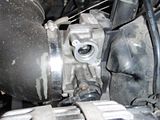
There are two sensors along the side of the TB. They are the Idle Air Control (IAC) Valve, and under it is the Throttle Positioning Sensor (TPS). Both are relatively easy to change out, and won't break the bank.
Here's the pic on mine.. hope it helps.
There are two sensors along the side of the TB. They are the Idle Air Control (IAC) Valve, and under it is the Throttle Positioning Sensor (TPS). Both are relatively easy to change out, and won't break the bank.
Here's the pic on mine.. hope it helps.
 07-20-2010, 07:43 AM
#4
I can't say that I was coding the same, but I can tell you that I ran into a similar situation.
There are two sensors along the side of the TB. They are the Idle Air Control (IAC) Valve, and under it is the Throttle Positioning Sensor (TPS). Both are relatively easy to change out, and won't break the bank.
Here's the pic on mine.. hope it helps.
There are two sensors along the side of the TB. They are the Idle Air Control (IAC) Valve, and under it is the Throttle Positioning Sensor (TPS). Both are relatively easy to change out, and won't break the bank.
Here's the pic on mine.. hope it helps.
07-20-2010, 07:48 AM
#5
Checked to see if i have a broken valve spring on the driver side but, they are good. It is also, not a plug wire either. Dont have another spare coil pack so, i am looking for a way to "bench" test it with a multimeter.
Last edited by mcfarlnd; 07-20-2010 at 05:42 PM.
Trending Topics
07-20-2010, 12:06 PM
#8

here is a bulletin on the p0068 code.
#PIP4578A: SES Light Idle Surge And/Or Reduced Engine Power Mode With DTCs P0068 P0121 P0506 P0507 P1516 P2101 P2119 And/Or P2176 - Clean Throttle Body And Perform Idle Learn Reset - (Feb 9, 2010)
Subject: SES Light, Idle Surge, and/or Reduced Engine Power Mode with DTCs P0068, P0121, P0506, P0507, P1516, P2101, P2119, and/or P2176 - Clean Throttle Body and Perform Idle Learn Reset
Models: 2007 Buick Rainier
2007-2009 Cadillac CTS-V, Escalade
2008-2009 Chevrolet Colorado
2006-2009 Chevrolet Avalanche, Corvette, Express, Impala, Monte Carlo, Silverado, Suburban, Tahoe, Trail Blazer
2008-2009 GMC Canyon
2006-2009 GMC Envoy, Savana, Sierra, Yukon
2007-2008 Hummer H2
2008-2009 Hummer H3
2007-2008 Pontiac Grand Prix
2008-2009 Pontiac G8
2006-2009 Saab 97x
With a V8 Engine
--------------------------------------------------------------------------------
This PI was superseded to update model years and add information concerning idle surge, reduced engine power mode, and/or DTCs P0068, P0121, P1516, P2101, P2119, and/or P2176 that may be experienced on high mileage vehicles. Please discard PIP4578.
--------------------------------------------------------------------------------
The following diagnosis might be helpful if the vehicle exhibits the symptom(s) described in this PI.
Condition/Concern:
As carbon builds up in the throttle body of a high mileage vehicle, the ECM/PCM learns to compensate by increasing the throttle plate angle.
If enough carbon builds up, an idle surge, deceleration surge, tip-in hesitation, reduced engine power mode, and/or DTCs P0068, P0121, P1516, P2101, P2119, and/or P2176 may be experienced on high mileage vehicles.
If the throttle body is cleaned without performing an "idle learn reset/reset idle learn" with the Tech 2, the ECM/PCM may continue to compensate for previous carbon build up, causing it to return with a similar concern as well as DTCs P0121, P0506, and/or P0507.
In a similar fashion, if the ECM/PCM of a high mileage vehicle is replaced and/or reprogrammed without performing the Throttle/Idle Learn outlined in SI, the ECM/PCM may no longer compensate for existing carbon build up in the throttle body, causing it to return with a similar concern as well as DTCs P0121, P0506, and/or P0507.
Recommendation/Instructions:
If SI diagnosis does not isolate the cause of this concern, inspect the throttle body bore and plate for obvious carbon build up.
If carbon is present, follow the Throttle Body Cleaning Procedure in SI to clean the throttle body.
After ensuring that the throttle body bore and plate are clean, perform an "idle learn reset/reset idle learn" with the Tech 2 and re-evaluate the concern.
Notice: Depending on the vehicle you are working on, the "idle learn reset/reset idle learn" is normally found on the Tech 2 ECM menu for Module Set Up or Special Functions/TAC System.
Please follow this diagnostic or repair process thoroughly and complete each step. If the condition exhibited is resolved without completing every step, the remaining steps do not need to be performed.
07-20-2010, 12:07 PM
#9
diag tree for the p0068 code.
Circuit Description
The powertrain control module (PCM) uses the following readings to calculate the predicted mass air flow (MAF) rate:
• The throttle position (TP)
• The barometric pressure (BARO)
• The intake air temperature (IAT)
• The engine RPM
The PCM compares the predicted MAF value to the actual MAF value, and to the speed density calculation, in order to verify the proper throttle operation.
DTC Descriptor
This diagnostic procedure supports the following DTC:
DTC P0068 Throttle Body Airflow Performance
Conditions for Running the DTC
• DTCs P0601, P0602, P0604, P0606, P1516, P2101, P2108, U0107 are not set.
• DTCs P0120 and P0220 are not active at the same time.
• The engine operates longer than 1 second.
• The engine speed is more than 500 RPM.
• DTC P0068 runs continuously once the above conditions are met.
Conditions for Setting the DTC
The PCM detects that the difference between the actual airflow and the speed density calculated air flow is greater than expected for more than 1.88 seconds.
Action Taken When the DTC Sets
• The control module illuminates the malfunction indicator lamp (MIL) when the diagnostic runs and fails.
• The control module records the operating conditions at the time the diagnostic fails. The control module stores this information in the Freeze Frame and/or the Failure Records.
• The control module commands the TAC system to operate in the Reduced Engine Power mode.
• A message center or an indicator displays Reduced Engine Power.
• Under certain conditions the control module commands the engine OFF.
Conditions for Clearing the MIL/DTC
• The control module turns OFF the malfunction indicator lamp (MIL) after 3 consecutive ignition cycles that the diagnostic runs and does not fail.
• A current DTC, Last Test Failed, clears when the diagnostic runs and passes.
• A history DTC clears after 40 consecutive warm-up cycles, if no failures are reported by this or any other emission related diagnostic.
• Clear the MIL and the DTC with a scan tool.
Diagnostic Aids
• Inspect the throttle blade for being broken, bent, or missing.
• Inspect the TP sensor for proper installation. A sensor that is misaligned could set this DTC.
• Inspect the throttle actuator control (TAC) module connectors for signs of water intrusion. If water intrusion occurs, multiple DTCs may set without any circuit or component conditions found during diagnostic testing.
• Physically and visually inspect the throttle body assembly and correct any problems that you observe. Manually move the throttle blade from closed to wide open throttle (WOT). You should not need to use excess force. The throttle blade should move smoothly through the full range, then should independently return to a slightly open position.
• When the TAC module detects a condition within the TAC system, more than one TAC system related DTC may set. This is due to the many redundant tests run continuously on this system. Locating and repairing one individual condition may correct more than one DTC. Disconnecting components during testing may set additional DTCs. Remember this if you review the stored information in Capture Info.
• For an intermittent condition, refer to Testing for Intermittent Conditions and Poor Connections .
Test Description
The numbers below refer to the step numbers on the diagnostic table.
This step will determine if the manifold absolute pressure (MAP) sensor voltage is within the proper range at idle.
This step will determine if the MAP sensor responds properly to the change in manifold pressure.
A throttle blade that sticks or binds may set this code. Opening the throttle through the entire range will indicate problems such as these.
When the PCM detects a condition within the electronic temperature control (ETC) system, other DTCs may set due to the many redundant tests run continuously on this system. Locating and repairing one individual condition may correct more than one DTC. Keep this in mind when reviewing captured DTC info.
Step
Action
Values
Yes
No
Schematic Reference: Engine Controls Schematics
Connector End View Reference: Powertrain Control Module Connector End Views or Engine Controls Connector End Views
1
Did you perform the Diagnostic System Check - Vehicle?
--
Go to Step 2
Go to Diagnostic System Check - Vehicle
2
Are any other DTCs set?
--
Go to Diagnostic Trouble Code (DTC) List - Vehicle
Go to Step 3
3
Observe the Freeze Frame/Failure Records for this DTC.
Turn OFF the ignition.
Start the engine.
Operate the vehicle within the Conditions for Running the DTC. You may also operate the vehicle within the conditions that you observed from the Freeze Frame/Failure Records.
Did the DTC fail this ignition?
--
Go to Step 4
Go to Diagnostic Aids
4
Inspect for the following conditions:
• Vacuum hoses for splits, kinks, and proper connections as shown on Vehicle Emission Control Information label--Inspect thoroughly for any type of leak or restriction.
• Air leaks at throttle body mounting area and intake manifold sealing surfaces
Did you find and correct the condition?
--
Go to Step 8
Go to Step 5
5
Allow the engine to reach operating temperature.
Observe the MAP sensor voltage parameter with a scan tool.
Is the manifold absolute pressure (MAP) sensor voltage within the specified range?
0.8-2 V
Go to Step 6
Go to DTC P0106
6
Idle the engine.
Observe the MAP sensor kPa parameter with a scan tool.
Increase the engine speed slowly and then back to idle.
Does the MAP sensor kPa change smoothly and gradually as engine speed is increased and returned to idle?
--
Go to Step 7
Go to DTC P0106
7
Caution: Turn OFF the ignition before inserting fingers into the throttle bore. Unexpected movement of the throttle blade could cause personal injury.
Inspect the throttle body for the following conditions while modulating the throttle through the entire range using the scan tool:
• Loose or damaged throttle blade
• Broken throttle shaft
• Drive mechanism damage
If any of the above conditions exist, replace the throttle body assembly. Refer to Throttle Body Assembly Replacement .
Did you find and correct the condition?
--
Go to Step 6
Go to Diagnostic Aids
8
Clear the DTCs with a scan tool.
Turn OFF the ignition for 30 seconds.
Start the engine.
Operate the vehicle within the Conditions for Running the DTC. You may also operate the vehicle within the conditions that you observed from the Freeze Frame/Failure Records.
Did the DTC fail this ignition?
--
Go to Step 2
Go to Step 7
9
Observe the Capture Info with a scan tool.
Are there any DTCs that have not been diagnosed?
--
Go to Diagnostic Trouble Code (DTC) List - Vehicle
System OK
07-20-2010, 12:09 PM
#10
bulletin for p106 code....
keywords DTC low MIL ping - (Jun 12, 2009)
Subject: Poor Acceleration from a Stop or Detonation in Gear at a Stop
Models: 1996-2009 All General Motors Passenger Cars and Light Duty Trucks
--------------------------------------------------------------------------------
This PI was superseded to update model years and add an important note. Please discard PIP3144B.
--------------------------------------------------------------------------------
The following diagnosis might be helpful if the vehicle exhibits the symptom(s) described in this PI.
Condition/Concern:
Customer concern of poor acceleration, detonation or "ping" at idle in drive or reverse, and/or possible DTC P0101, P0106 and/or P0121 set in the PCM. The vehicle will perform properly after attaining a speed of about 30 - 40 mph. The condition may also be described by the customer or the dealer as a hesitation, stall when putting into gear, surge on acceleration (similar to hitting fuel cut off or rev limiter). The ultimate cause may be a non-holding torque converter stator or damaged stator support shaft within the automatic transmission.
Recommendation/Instructions:
Important Note: Do not follow the below diagnostics until published SI diagnostics have been followed COMPLETELY. If all published SI diagnostics have been exhausted the following information may help in isolating a possible torque converter concern.
The following checks should be performed in the event that normal engine driveability checks have not resolved the detonation or "ping" at idle in drive or reverse, lack of power from a stop, stall, and surge on acceleration and or hesitation complaint.
The IAC counts throttle angle and/or MAP voltage and KPA should be compared to a like vehicle in park and in gear after reaching operating temperature. If the counts and map are high or throttle angle is open excessively in comparison this may be a result of high engine load and a torque converter and or stator support shaft related concern.
If the above information does not lead to resolution, follow torque converter diagnostics listed below:
The transmission oil cooler outlet line (line to the cooler) should be checked for excessive heat. The Tech II scan tool may be helpful on vehicles equipped with the transmission fluid temperature sensor in the cooler line (mainly front wheel drive). On vehicles that do not have the temperature sensor in the cooler line a temperature probe should be used to check the temperature. The temperature readings should be compared to a like vehicle with the same powertrain option content.
A stall test (brake torque) may point to a damaged torque converter; the stall rpm speed will be lower than a like vehicle. However, poor engine performance will also produce a lower stall speed rpm.
If the torque converter stator or stator support is suspect, the transmission should be removed and THE STATOR SUPPORT SHOULD BE INSPECTED FOR SPLINE DAMAGE. If the stator support splines are damaged the transmission should be repaired and new torque converter installed. If damage is not present on the stator support the concern is either internal to the torque converter stator or an engine performance concern.
Please follow this diagnostic or repair process thoroughly and complete each step. If the condition exhibited is resolved without completing every step, the remaining steps do not need to be performed