P0068, P0106 and **REP**
 07-20-2010, 12:12 PM
#11

diag tree for the p0106 code...hope this helps ya some Jim.
Service Information
2007 Chevrolet Silverado Classic - 2WD | Document ID: 1714479
--------------------------------------------------------------------------------
DTC P0106
Diagnostic Instructions
• Perform the Diagnostic System Check - Vehicle prior to using this diagnostic procedure.
• Review Strategy Based Diagnosis for an overview of the diagnostic approach.
• Diagnostic Procedure Instructions provides an overview of each diagnostic category.
DTC Descriptor
DTC P0106: Manifold Absolute Pressure (MAP) Sensor Performance
Diagnostic Fault Information
Circuit
Short to Ground
High Resistance
Open
Short to Voltage
Signal Performance
5-Volt Reference
P0101, P0107, P0522, P0641
P0106, P0107
P0107
P0101, P0106, P0108, P0522, P0641
P0106, P0107
MAP Sensor Signal
P0107
P0106, P0107
P0107
P0108
P0106, P0107
Low Reference
--
P0106, P0108
P0106, P0108
--
P0106, P0108
Typical Scan Tool Data
MAP Sensor Circuit
Normal Range
Short to Ground
Open
Short to Voltage
5-Volt Reference
--
10 kPa
10 kPa
104 kPa
MAP Sensor Signal
12-103 kPa
10 kPa
10 kPa
104 kPa
Low Reference
--
--
80-103 kPa
--
Circuit Description
The manifold absolute pressure (MAP) sensor responds to pressure changes in the intake manifold. The pressure changes occur based on the engine load. The MAP sensor has the following circuits:
• A 5-volt reference circuit
• A low reference circuit
• A MAP sensor signal circuit
The powertrain control module (PCM) supplies 5 volts to the MAP sensor on the 5-volt reference circuit. The PCM also provides a ground on the low reference circuit. The MAP sensor provides a signal to the PCM on the MAP sensor signal circuit which is relative to the pressure changes in the manifold. The PCM should detect a low signal voltage at a low MAP, such as during an idle or deceleration. The PCM should detect a high signal voltage at a high MAP, such as the ignition ON, with the engine OFF, or at wide open throttle (WOT). The MAP sensor is also used to in order to determine the barometric pressure (BARO). This occurs when the ignition switch is turn ON, with the engine OFF. The BARO reading may also be updated whenever the engine is operated at WOT. The PCM monitors the MAP sensor signal for voltage outside of the normal range.
The PCM calculates a predicted value for the MAP sensor based on the throttle position (TP) and the engine speed. The PCM then compares the predicted value to the actual MAP sensor signal. If the PCM detects that the MAP sensor signal is not within the predicted range, DTC P0106 sets.
Conditions for Running the DTC
• DTCs P0068, P0107, P0108, P0120, P0220, P0506, P0507, P2135 are not set.
• The engine speed is between 500-5,000 RPM.
• Any change in the engine speed is less than 125 RPM.
• The change in air flow is less than 10 g/s.
• The traction control, if equipped, is not active.
• The power take-off (PTO), if equipped, is not active.
• The A/C compressor clutch state does not change.
• The clutch switch state does not change, if equipped with a manual transmission.
• The power steering load is stable.
• The brake switch state does not change.
• The above conditions are met for 1 second.
• DTC P0106 runs continuously when the above conditions are met.
Conditions for Setting the DTC
The PCM detects that the MAP sensor signal is not within the predicted range for 2 seconds.
Action Taken When the DTC Sets
• The control module illuminates the malfunction indicator lamp (MIL) on the second consecutive ignition cycle that the diagnostic runs and fails.
• The control module records the operating conditions at the time the diagnostic fails. The first time the diagnostic fails, the control module stores this information in the Failure Records. If the diagnostic reports a failure on the second consecutive ignition cycle, the control module records the operating conditions at the time of the failure. The control module writes the operating conditions to the Freeze Frame and updates the Failure Records.
Conditions for Clearing the MIL/DTC
• The control module turns OFF the malfunction indicator lamp (MIL) after 3 consecutive ignition cycles that the diagnostic runs and does not fail.
• A current DTC, Last Test Failed, clears when the diagnostic runs and passes.
• A history DTC clears after 40 consecutive warm-up cycles, if no failures are reported by this or any other emission related diagnostic.
• Clear the MIL and the DTC with a scan tool.
Reference Information
Schematic Reference
Engine Controls Schematics
Connector End View Reference
• Engine Controls Connector End Views
• Powertrain Control Module Connector End Views
Electrical Information Reference
• Circuit Testing
• Connector Repairs
• Testing for Intermittent Conditions and Poor Connections
• Wiring Repairs
Scan Tool Reference
• Scan Tool Data List
• Scan Tool Output Controls
Circuit/System Verification
Important: Verify that the engine is in good mechanical condition before continuing with this diagnostic.
• Verify the integrity of the air induction system by inspecting for the following conditions:
- Any damaged components
- Loose or improper installation
- Improperly routed vacuum hoses
- Any vacuum leak
- Any type of restriction
- A MAP sensor seal that is missing or damaged
• Verify that restrictions do not exist in the MAP sensor vacuum source.
• Verify that restrictions do not exist in the exhaust system. Refer to Restricted Exhaust .
• A skewed or stuck engine coolant temperature (ECT) or IAT sensor will cause the calculated models to be inaccurate and may cause this DTC to run when it should not. Refer to Temperature Versus Resistance .
• The BARO that is used by the PCM to calculate the air flow models is initially based on the MAP sensor at ignition ON. When the engine is running, the PCM will continually update the BARO value near wide open throttle using the MAP sensor and a calculation. A skewed MAP sensor will cause the BARO value to be inaccurate. Use the scan tool and compare the BARO parameter at ignition ON to the Altitude vs. Barometric Pressure Table. Refer to Altitude Versus Barometric Pressure .
• A skewed MAP sensor will also cause the first and second intake manifold models to disagree with the actual MAP sensor measurements. Use the scan tool and compare the MAP Sensor parameter to a known good vehicle, under various operating conditions.
• Inspect for the following conditions:
- Incorrect cam timing--Refer to Timing Chain and Sprocket Replacement .
- Worn piston rings--Refer to Engine Compression Test .
Circuit/System Testing
Turn ON the ignition, with the engine OFF.
Disconnect the MAP sensor.
Important: Certain resistances will not be detectable if a test lamp is not connected to provide a circuit load.
Connect a test lamp between the MAP sensor 5-volt reference circuit and a good ground.
Measure for a proper range of 4.8-5.2 volts between the MAP sensor 5-volt reference circuit and a good ground.
⇒ If the voltage is less than the specified range, then test the circuit for an open, or high resistance. If the circuit tests normal, replace the PCM.
⇒ If the voltage is more than the specified range, then test the circuit for a short to voltage. If the circuit tests normal, replace the PCM.
With the MAP sensor still disconnected, use the scan tool to observe the MAP Sensor parameter for the proper value of less than 12 kPa.
⇒ If the MAP Sensor parameter is more than 12 kPa, then test the MAP sensor signal circuit for a short to voltage. If the circuit tests normal, replace the PCM.
Connect a 3-amp jumper wire between the MAP sensor 5-volt reference circuit and the MAP sensor signal circuit.
Use the scan tool to observe the MAP Sensor parameter for the proper value of more than 103 kPa.
⇒ If the MAP Sensor parameter is less than 103 kPa, then test the MAP sensor signal circuit for high resistance. If the circuit tests normal, replace the PCM.
Turn OFF the ignition, and all electrical accessories. Allow sufficient time for the control module to power down before taking a resistance measurement.
Measure for a proper value of less than 10 ohms of resistance between the low reference circuit of the MAP sensor and a good ground.
⇒ If the resistance is more than 10 ohms, then test the circuit for high resistance. If the circuit tests normal, replace the PCM.
If the MAP sensor circuits test normal, then replace the MAP sensor.
Repair Instructions
Perform the Diagnostic Repair Verification after completing the diagnostic procedure.
• Manifold Absolute Pressure Sensor Replacement
• Control Module References for PCM replacement, setup, and programming

 07-20-2010, 05:50 PM
#18
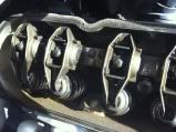
I finally got to pull the passenger side valve cover off and guess what i find...........Broken Valve Spring, valve still in the retainer and locks. valve hasnt dropped into the piston by the grace of GOD himself. Thanks for all the input everyone and ERIC, YOU TOLD ME SO!!!!!!!!!!!!!!!!!!!!!!!
 I guess ill be putting my new heads on now a little ahead of schedule. Ill put up pics as soon as my buddy emails me them from his I-Phone.
valve hasnt dropped into the piston by the grace of GOD himself. Thanks for all the input everyone and ERIC, YOU TOLD ME SO!!!!!!!!!!!!!!!!!!!!!!! I guess ill be putting my new heads on now a little ahead of schedule. Ill put up pics as soon as my buddy emails me them from his I-Phone.