Running An Autometer Wide Band O2 Sensor With Hp Tuners
#1
For those of you that use HPTuners Pro for tuning and add a wideband (with outputs for a data logger) you most likely purchased a wideband that already is populated in the VCM scanner therefore it is a simple click and insert to begin logging. The most popular ones that already are set-up in HPT include: AEM, LC1 (innovate), PLX, FJO and DynoJet to name a few. Well, I wanted to be different and also wanted my aftermarket gauges to match the Silverado SS gauge cluster so I purchased an Autometer wideband O2 gauge in the Phantom series. The challenge is that in order to use the outputs from the wideband in HPT, you need to configure a custom User Defined EIO Auxiliary input so that you have accurate data to tune with. Here is how I did it:
Step 1 – Set-up your Autometer Wideband to read from 10 – 16 AFR’s. I chose these values for accuracy sake. I know the meter can read wider than that however who really cares about outside that range. I would rather have more accurate data over a tighter use-able range than less accurate data over a wider range. Setting a 10-16AFR range is critical before continuing so follow the instructions that Autometer includes with the Wide Band O2 Meter to set up as 10-16 AFR's.
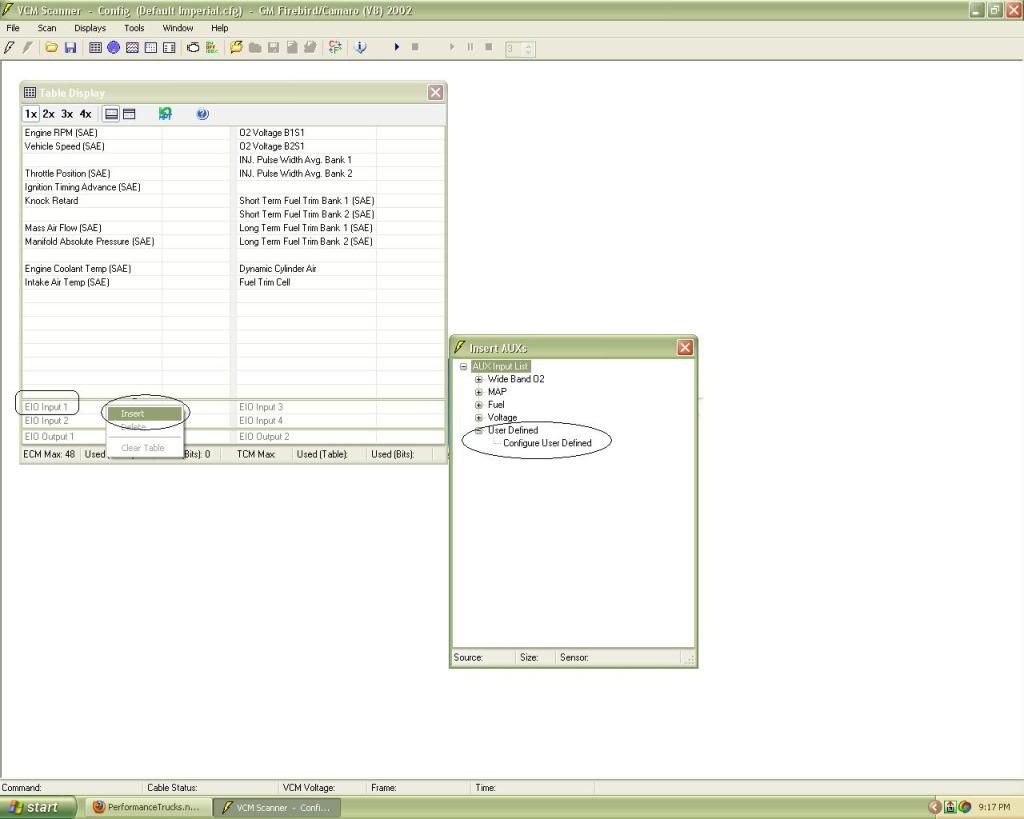
Step 2 – Create a custom EIO Aux. input. Open the VCM scanner, use the Default Imperial Configuration and click on “Display” “Table View” (See Illustration 1). Right click on the “EIO Input 1” allowing a new window to pop up with three choices. Choose “Insert” (See Illustration 1). When you click on “Insert” a new window pops up called “Insert AUX’s”. Looking at this tree of choices, click on “User Defined” and then double click on “Configure User Defined” (See Illustration 1).
Illustration 1:

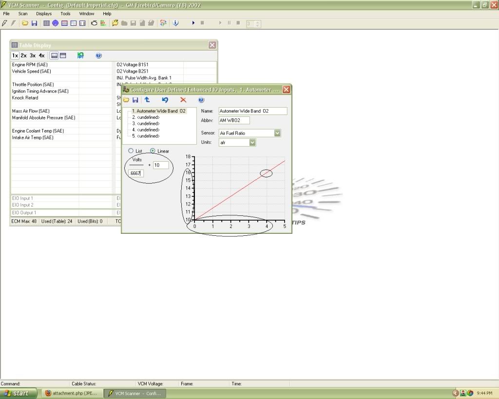
You should now have a “Configure User Defined Enhanced IO Input” table opened (See Illustration 2). This is the table where some math is involved. Click once on the first line item ( 1. <undefined>). To the right, name your EIO input 1. I chose to keep it simple and call it “Autometer Wide Band O2” (See Illustration 2). Just under that, give it an abbreviation of your choice. The next line is a drop down menu for “sensor” of which you should choose “Air Fuel Ratio”. Finally, select the units which will be “afr”.
Illustration 2:

We are now going to write the formula for the Autometer WB O2 gauge in the same table. Remember that we set our Autometer WB to accurately read between 10 and 16 AFR’s in step one. That is critical for this formula here. Another critical bit of information that must be recognized is that the outputs on the Autometer WB are linear from 0 to 4 volts whereas most wideband outputs are 0-5V. Now that we know the output is given in a linear scale of 0-4V and that the gauge is set-up to read 10 to 16 AFR’s (range of 6 AFR’s), we now need to calculate the slope of that line.
For simplicity sake, we will define slope as Rise / Run.
Slope = Rise / Run = 4 (Volts) / 6 (AFR's) = 0.6667
The slope of a linear line with a rise of 4 and a run of 6 is 0.6667. This is correct if we are reading AFR’s starting at 0 and going to 6 however we are not. The solution is to add a base 10 to our formula to shift the slope from 0-6AFR’s to a 10-16AFR’s.
Now let’s take all of those calculations and plug them into our “Configure User Defined Enhanced IO Input” table. Looking at Illustration 2, you will want to click on “Linear” and fill in the denominator with our calculated slope value from above which is 0.6667. In the next open field of the equation, we must enter “10” to shift our linear slope from 0-6AFR’s to 10-16AFR’s as mentioned above. Now, looking at the graph that results from our formula, you can see that the slope of the line intersects the point of the graph at 4 volts and 16AFR’s (See Illustration 2 where the intercept of 4 volts and 16 AFR is circled). This indicates to us that when the Wide Band puts out a 4 volt signal, it will correlate to an AFR of 16. Being that the scale is linear, you can see that 2 volts equates to 13 AFR’s and so on.
Once you are sure your formula is correct, click on the “commit changes” icon to save your changes to the EIO-1. Your table display should now show “Autometer Wide Band O2” or whatever you named it in the EIO-1 input location!
Now go to “File”, “Save Configuration As” and save all of this hard work. I personally call this configuration “Default Imperial AM Wideband”.
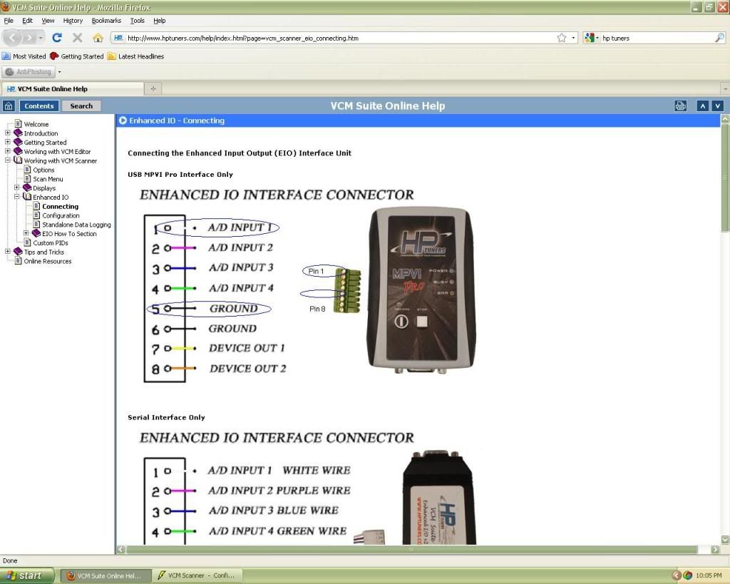
Step 3 – Hooking up your wideband to the HP Tuners EIO Interface connector. There are two output wires from the Autometer Wide Band (Blue and a Blue / Black). The blue wire is the + signal wire and should go to PIN 1 on the interface. The Blue/Black is the ground wire and needs to go to PIN 5 on the interface (See Illustration 3).
Illustration 3:

Now fire up your truck, open the new configuration you just made and begin logging. You should be able to see your AFR on the chart display since the WB sensor parameter has already been inserted in chart 2 of the Chart Display. I now suggest looking into setting up some histograms using your new Wide Band and discover the importance of the WB for fuel tuning!
...I did not get into correcting for a voltage offset in my write-up however correcting for a voltage offset involves the same formula I outlined above by just adding the offset difference to the base 10 number. A detailed explanation can be found here: http://www.hptuners.com/forum/showth...light=wideband
Step 1 – Set-up your Autometer Wideband to read from 10 – 16 AFR’s. I chose these values for accuracy sake. I know the meter can read wider than that however who really cares about outside that range. I would rather have more accurate data over a tighter use-able range than less accurate data over a wider range. Setting a 10-16AFR range is critical before continuing so follow the instructions that Autometer includes with the Wide Band O2 Meter to set up as 10-16 AFR's.
Step 2 – Create a custom EIO Aux. input. Open the VCM scanner, use the Default Imperial Configuration and click on “Display” “Table View” (See Illustration 1). Right click on the “EIO Input 1” allowing a new window to pop up with three choices. Choose “Insert” (See Illustration 1). When you click on “Insert” a new window pops up called “Insert AUX’s”. Looking at this tree of choices, click on “User Defined” and then double click on “Configure User Defined” (See Illustration 1).
Illustration 1:

You should now have a “Configure User Defined Enhanced IO Input” table opened (See Illustration 2). This is the table where some math is involved. Click once on the first line item ( 1. <undefined>). To the right, name your EIO input 1. I chose to keep it simple and call it “Autometer Wide Band O2” (See Illustration 2). Just under that, give it an abbreviation of your choice. The next line is a drop down menu for “sensor” of which you should choose “Air Fuel Ratio”. Finally, select the units which will be “afr”.
Illustration 2:

We are now going to write the formula for the Autometer WB O2 gauge in the same table. Remember that we set our Autometer WB to accurately read between 10 and 16 AFR’s in step one. That is critical for this formula here. Another critical bit of information that must be recognized is that the outputs on the Autometer WB are linear from 0 to 4 volts whereas most wideband outputs are 0-5V. Now that we know the output is given in a linear scale of 0-4V and that the gauge is set-up to read 10 to 16 AFR’s (range of 6 AFR’s), we now need to calculate the slope of that line.
For simplicity sake, we will define slope as Rise / Run.
Slope = Rise / Run = 4 (Volts) / 6 (AFR's) = 0.6667
The slope of a linear line with a rise of 4 and a run of 6 is 0.6667. This is correct if we are reading AFR’s starting at 0 and going to 6 however we are not. The solution is to add a base 10 to our formula to shift the slope from 0-6AFR’s to a 10-16AFR’s.
Now let’s take all of those calculations and plug them into our “Configure User Defined Enhanced IO Input” table. Looking at Illustration 2, you will want to click on “Linear” and fill in the denominator with our calculated slope value from above which is 0.6667. In the next open field of the equation, we must enter “10” to shift our linear slope from 0-6AFR’s to 10-16AFR’s as mentioned above. Now, looking at the graph that results from our formula, you can see that the slope of the line intersects the point of the graph at 4 volts and 16AFR’s (See Illustration 2 where the intercept of 4 volts and 16 AFR is circled). This indicates to us that when the Wide Band puts out a 4 volt signal, it will correlate to an AFR of 16. Being that the scale is linear, you can see that 2 volts equates to 13 AFR’s and so on.
Once you are sure your formula is correct, click on the “commit changes” icon to save your changes to the EIO-1. Your table display should now show “Autometer Wide Band O2” or whatever you named it in the EIO-1 input location!
Now go to “File”, “Save Configuration As” and save all of this hard work. I personally call this configuration “Default Imperial AM Wideband”.
Step 3 – Hooking up your wideband to the HP Tuners EIO Interface connector. There are two output wires from the Autometer Wide Band (Blue and a Blue / Black). The blue wire is the + signal wire and should go to PIN 1 on the interface. The Blue/Black is the ground wire and needs to go to PIN 5 on the interface (See Illustration 3).
Illustration 3:

Now fire up your truck, open the new configuration you just made and begin logging. You should be able to see your AFR on the chart display since the WB sensor parameter has already been inserted in chart 2 of the Chart Display. I now suggest looking into setting up some histograms using your new Wide Band and discover the importance of the WB for fuel tuning!
...I did not get into correcting for a voltage offset in my write-up however correcting for a voltage offset involves the same formula I outlined above by just adding the offset difference to the base 10 number. A detailed explanation can be found here: http://www.hptuners.com/forum/showth...light=wideband

#5
damn nice how to!!! I am running this same exact wide band, but I will be tuned with EFI Live, not sure if they support the autometer, but this is something Justin should look into just in case.
awesome write up Kevin -
awesome write up Kevin -

#6
Yea, that is the issue I have. Pretty much all of the info is hidden in the forum however not in a step by step or explaining the "How's and "Why's". I figured since the AM Wide Bands are starting to become popular, this could be useful to someone starting out.
Thanks guys, hopefully it benefits someone out there...
Trending Topics
Thread
Thread Starter
Forum
Replies
Last Post
KINGCYCLES
GM Parts Classifieds
1
10-02-2015 11:21 AM


