
Throtte Body Gremlins...!~@#$%^&*

 09-05-2011, 02:16 PM
#12
TECH Addict
iTrader: (25)
Join Date: Dec 2004
Location: southern california
Posts: 2,913
Likes: 0
Received 0 Likes
on
0 Posts
the the v2 of the tqrush harness will control both tb's but im just saying that may not be the problem . ive seen the stock pigtail to the tb get broken inner copper and be fine on the outside , causing interminute problems like your having , i had to replace mine on my ss and gm thought that it would be fun to make the new pigtail wires all the same color instead of color coded like stock . the wire can break about 6-8 inches from the connector itself. id try pulling everything and running a 78mm if possible to eliminate some variables from this equation.
09-05-2011, 02:25 PM
#13
TECH Fanatic
Thread Starter
iTrader: (47)

Join Date: Oct 2008
Location: 714
Posts: 1,715
Likes: 0
Received 0 Likes
on
0 Posts
i have already removed 6" of wire from the harness and repinned the TB connector. Still gets the exact same codes. the x link is brand new.
an 87mm 3 bolt TB wont bolt up to my blower anyway.
an 87mm 3 bolt TB wont bolt up to my blower anyway.
 09-05-2011, 08:16 PM
#16
The first 6 codes Listed were initailly set in the system.
After repairing the Tb wiring harness and clearing the DTC's. The following DTC's P1515 and P2135 were set and would not clear. After starting it, we had P0220, P1515, P1518, P2135.
After repairing the Tb wiring harness and clearing the DTC's. The following DTC's P1515 and P2135 were set and would not clear. After starting it, we had P0220, P1515, P1518, P2135.
 09-05-2011, 08:33 PM
#19
i believe P1518 is what we need to go after. It states to chase the wiring and check for short to voltage on Tac module ground circuit and or check for open or short on the Tac module data circuit.
How ever I can not find any info P0220 or P2135 related to this truck...
P1515 states the comanded throttle position and the actual throttle possitions are not within calibrated range of each other.
Need to see the wiring diaghram but maybe the Pedel is the issue. will have to rule out the wiring first and check the individual circuits and make sure each part is withen spec.
09-05-2011, 08:37 PM
#20
I assume that the battery is well charged?
Are you sure that you have the 8 pin connector pinned correctly? There are two 5V and two 0V circuits that are not interchangeable.
DTC P1515
Circuit Description
The commanded throttle position (TP), based on accelerator pedal position (APP) and possibly other limiting factors, is compared to the actual TP. The 2 values should be within a calibrated range of each other. Both the powertrain control module (PCM) and the throttle actuator control (TAC) module redundantly monitor the commanded and actual TP. This DTC sets if the PCM detects an out-of-range condition between commanded and actual throttle position.
Conditions for Running the DTC
Circuit Description
The throttle actuator control (TAC) module and the powertrain control module (PCM) communicate via a dedicated serial data circuit. This serial data circuit is separate from any other serial data circuit on the vehicle. Accurate transmitting and receiving of serial data requires not only good circuit integrity but also adequate system voltage. This diagnostic test monitors the accuracy of the serial data transmitted between the TAC module and the PCM. If the PCM detects a loss of data or invalid data, this DTC sets.
Conditions for Running the DTC
Important: Reprogramming the PCM may cause a communication error between the PCM and the TAC. If the PCM detects a communication error, DTC P1518 sets. Clear any DTCs from the memory that may have been set by Reprogramming.
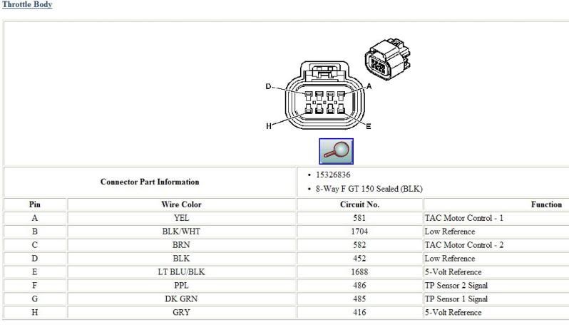
Are you sure that you have the 8 pin connector pinned correctly? There are two 5V and two 0V circuits that are not interchangeable.
DTC P1515
Circuit Description
The commanded throttle position (TP), based on accelerator pedal position (APP) and possibly other limiting factors, is compared to the actual TP. The 2 values should be within a calibrated range of each other. Both the powertrain control module (PCM) and the throttle actuator control (TAC) module redundantly monitor the commanded and actual TP. This DTC sets if the PCM detects an out-of-range condition between commanded and actual throttle position.
Conditions for Running the DTC
- DTCs P0601, P0602, P0604, P0606, P1516, P1518, P2108 are not set.
- DTCs P0120, P0220, P2135 are not active at the same time.
- DTCs P0120 and P0220 are not active at the same time.
- The ignition switch is in the crank or run position.
- The ignition voltage is more than 8.5 volts.
- The TAC system is not in the battery saver mode.
- The PCM detects that the commanded and actual throttle positions are not within a calibrated range of each other.
- The above condition is met for less than 1 second.
- The control module illuminates the malfunction indicator lamp (MIL) when the diagnostic runs and fails.
- The control module records the operating conditions at the time the diagnostic fails. The control module stores this information in the Freeze Frame and/or the Failure Records.
- The control module commands the TAC system to operate in the Reduced Engine Power mode.
- A message center or an indicator displays Reduced Engine Power.
- Under certain conditions the control module commands the engine OFF.
- The control module turns OFF the malfunction indicator lamp (MIL) after 3 consecutive ignition cycles that the diagnostic runs and does not fail.
- A current DTC, Last Test Failed, clears when the diagnostic runs and passes.
- A history DTC clears after 40 consecutive warm-up cycles, if no failures are reported by this or any other emission related diagnostic.
- Clear the MIL and the DTC with a scan tool.
- Inspect for mechanical concerns or binding that may be temperature related. Components may not move freely in extreme heat or cold due to the presence of contaminants or ice formation.
- Inspect the TAC module connectors for signs of water intrusion. If water intrusion occurs, multiple DTCs may set without any circuit or component conditions found during diagnostic testing.
- When the TAC module detects a condition within the TAC system, more than 1 TAC system related DTC may set. This is due to the many redundant tests run continuously on this system. Locating and repairing an individual condition may correct more than 1 DTC. Disconnecting components during testing may set additional DTCs. Remember this if you review the stored information in Capture Info.
- For an intermittent, refer to Intermittent Conditions .
Circuit Description
The throttle actuator control (TAC) module and the powertrain control module (PCM) communicate via a dedicated serial data circuit. This serial data circuit is separate from any other serial data circuit on the vehicle. Accurate transmitting and receiving of serial data requires not only good circuit integrity but also adequate system voltage. This diagnostic test monitors the accuracy of the serial data transmitted between the TAC module and the PCM. If the PCM detects a loss of data or invalid data, this DTC sets.
Conditions for Running the DTC
- The ignition switch is in the crank or run position.
- The ignition voltage is more than 5.23 volts.
- Invalid or missing serial data messages are detected for a predetermined amount of time.
- The above condition is met for more than 1 second.
- The control module illuminates the malfunction indicator lamp (MIL) when the diagnostic runs and fails.
- The control module records the operating conditions at the time the diagnostic fails. The control module stores this information in the Freeze Frame and/or the Failure Records.
- The control module commands the TAC system to operate in the Reduced Engine Power mode.
- A message center or an indicator displays Reduced Engine Power.
- Under certain conditions the control module commands the engine OFF.
- The control module turns OFF the malfunction indicator lamp (MIL) after 3 consecutive ignition cycles that the diagnostic runs and does not fail.
- A current DTC, Last Test Failed, clears when the diagnostic runs and passes.
- A history DTC clears after 40 consecutive warm-up cycles, if no failures are reported by this or any other emission related diagnostic.
- Clear the MIL and the DTC with a scan tool.
Important: Reprogramming the PCM may cause a communication error between the PCM and the TAC. If the PCM detects a communication error, DTC P1518 sets. Clear any DTCs from the memory that may have been set by Reprogramming.
- DTC P1518 sets if the battery voltage is low. If the customer's concern is slow cranking or no crank because battery voltage is low, ignore DTC P1518. Clear any DTCs from memory that may have set from the low battery voltage condition.
- DTC P1518 sets when there is a short to B+ on the TAC module ground circuit. Inspect the fuses for the circuits that are in the TAC module harness--i.e. cruise, brake. An inspection of the fuses may lead you to the circuit that is shorted to the TAC module ground circuit.
- DTC P1518 sets if the TAC module ignition feed circuit is shorted to a B+ supply circuit. The TAC module stays powered-up when the ignition switch is turned OFF. When the ignition switch is turned ON, the TAC module is powered-up before the PCM. DTC P1518 sets because no communication is detected by the TAC module from the PCM. Inspect related circuits for being shorted to a B+ supply circuit.
- Inspect the TAC module power and ground circuits and the TAC module/PCM serial data circuits for intermittent connections.
- Inspect the TAC module connectors for signs of water intrusion. If water intrusion occurs, multiple DTCs may set without any circuit or component conditions found during diagnostic testing.
- When the TAC module detects a problem within the TAC system, more than 1 TAC system related DTC may set. This is due to the many redundant tests run continuously on this system. Locating and repairing an individual condition may correct more than 1 DTC. Remember this if you review the stored information in Capture Info.
- For an intermittent condition, refer to Intermittent Conditions .
Last edited by DrX; 09-05-2011 at 08:44 PM.