Throtte Body Gremlins...!~@#$%^&*


 09-07-2011, 02:11 PM
#52
TECH Fanatic
Thread Starter
iTrader: (47)

Join Date: Oct 2008
Location: 714
Posts: 1,715
Likes: 0
Received 0 Likes
on
0 Posts
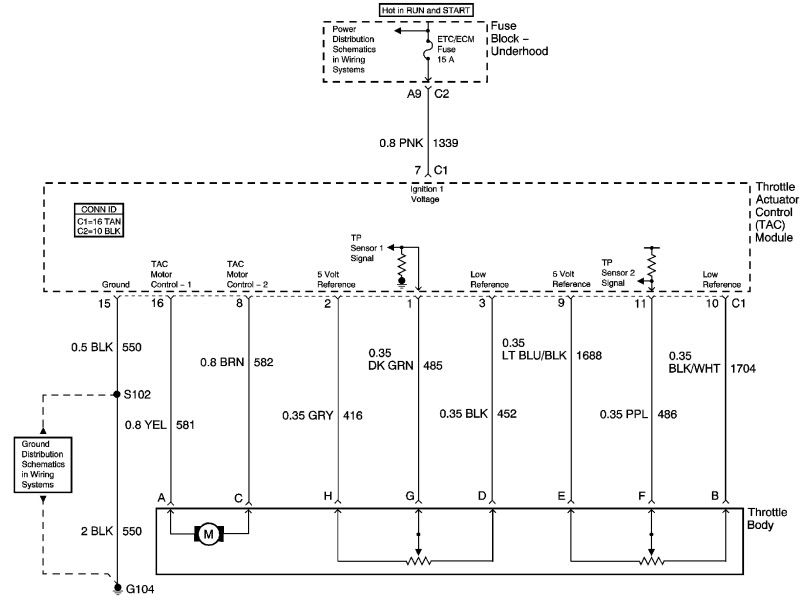
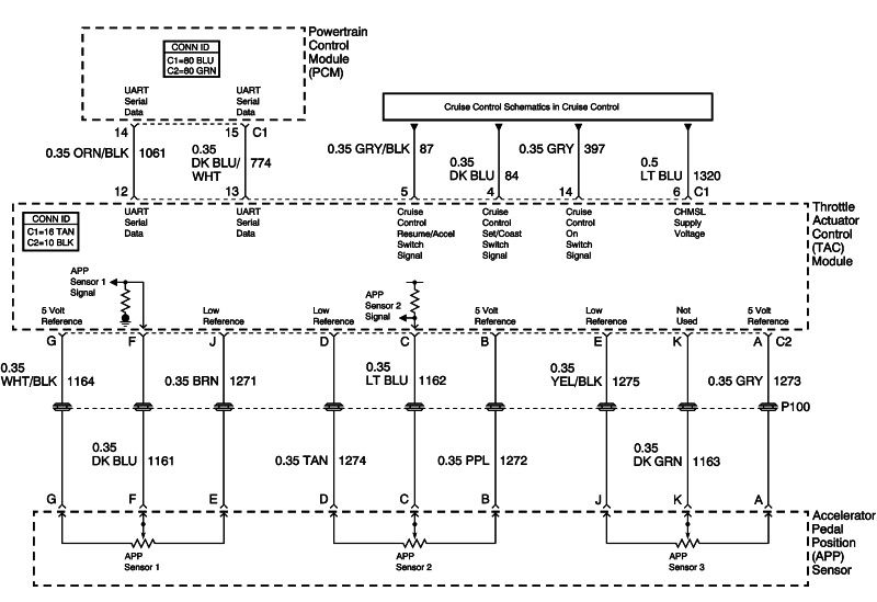
I am hoping its just a wire....now to find that wire...hard to even find a place to start and find the reference as to what the wire is supposed to be doing based on key position engine running etc.
 09-07-2011, 02:26 PM
#54
TECH Fanatic
Thread Starter
iTrader: (47)
Join Date: Oct 2008
Location: 714
Posts: 1,715
Likes: 0
Received 0 Likes
on
0 Posts
i have checked that....it has actually been moved for quite a long time to the firewall lug....i waqs going to try and reconnect it to the back of the block next time i am at the shop. the bolt is a complete PITA. wish i would have done it with the trans out.
09-07-2011, 05:48 PM
#58
HPT setting
TPS Sensor
P0121 Max MAP: The VCM will calculate an expected TPS position in two MAP ranges. If the MAP is less than MinMAP then it will use one table to calculated expected TPS, if MAP is greater than MaxMAP it will use a different TPS calculation table. To disable this test set MaxMAP to 100.
P0121 Min MAP: The VCM will calculate an expected TPS position in two MAP ranges. If the MAP is less than MinMAP then it will use one table to calculated expected TPS, if MAP is greater than MaxMAP it will use a different TPS calculation table. To disable this test set MinMAP to 0.
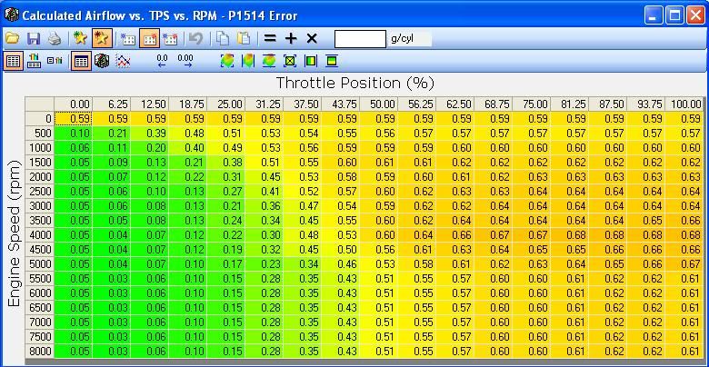
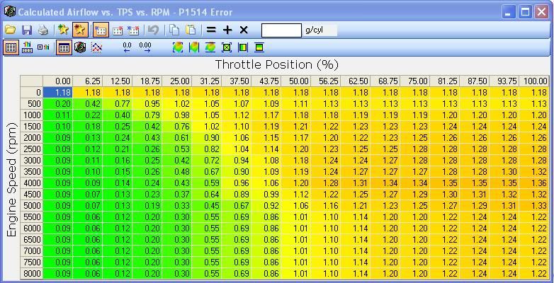
Calculated Airflow vs. TPS% vs. RPM - P1514/P0068 Error: The VCM uses this table to determine the maximum airflow/cylair the Electronic Throttle should be passing at a certain TPS position and RPM. If the measured cylair/airflow exceeds this value then P1514/P0068 is set.
OE
Blower
MAP Sensor
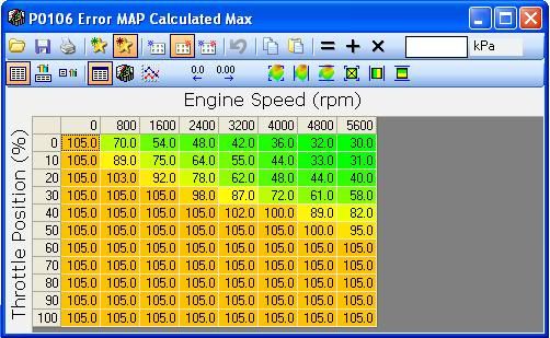
The VCM calculates a predicted MAP signal based on current TPS and RPM. If the measured MAP is out of range then P0106 is set. This can be a problem for supercharged vehicles.
P0106 MAP Test Max: This table specifies the maximum MAP predicted based on TPS and RPM.
P0106 MAP Test Min: This table specifies the minimum MAP predicted based on TPS and RPM.
OE P0106 Max
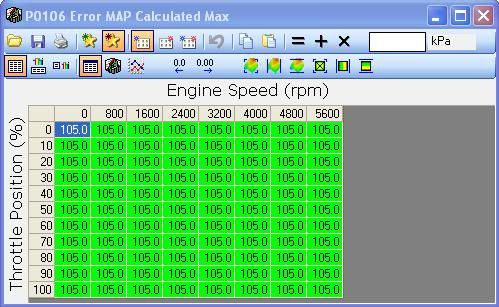
Blower P0106 Max
TPS Sensor
P0121 Max MAP: The VCM will calculate an expected TPS position in two MAP ranges. If the MAP is less than MinMAP then it will use one table to calculated expected TPS, if MAP is greater than MaxMAP it will use a different TPS calculation table. To disable this test set MaxMAP to 100.
P0121 Min MAP: The VCM will calculate an expected TPS position in two MAP ranges. If the MAP is less than MinMAP then it will use one table to calculated expected TPS, if MAP is greater than MaxMAP it will use a different TPS calculation table. To disable this test set MinMAP to 0.
Calculated Airflow vs. TPS% vs. RPM - P1514/P0068 Error: The VCM uses this table to determine the maximum airflow/cylair the Electronic Throttle should be passing at a certain TPS position and RPM. If the measured cylair/airflow exceeds this value then P1514/P0068 is set.
OE
Blower
MAP Sensor
The VCM calculates a predicted MAP signal based on current TPS and RPM. If the measured MAP is out of range then P0106 is set. This can be a problem for supercharged vehicles.
P0106 MAP Test Max: This table specifies the maximum MAP predicted based on TPS and RPM.
P0106 MAP Test Min: This table specifies the minimum MAP predicted based on TPS and RPM.
OE P0106 Max
Blower P0106 Max